4
1.1 UNPACKING
Remove all packaging material.•
Remove separate accessory box.•
Remove the generator from carton.•
1.1.1 ACCESSORY BOX
Check all contents. If any parts are missing or damaged locate an
authorized dealer at 1-888-436-3722.
Contents Include:
1 – Owner’s Manual • 1 - Left Handle Assembly•
1 - Quart Oil SAE 30 • 1 - Right Handle Assembly•
2 - Never-Flat Wheels • 1 - Frame Foot•
1 - 12 volt Adapter Plug • 1 - Foot Support•
Charger*
1 - Hardware Bag (containing the following):•
2 - Rubber Feet 2 - 5/16” Bolts
2 - 5/16” Flat Washers 4 - 5/16” Locking Flange Nuts
4 - 5/16” Carriage Bolts 2 - 5/16” Locking Cap Nuts
2 - 1/2” Axle Bolts 2 - 1/2” Locking Flange Nuts
2 - 1/2" Flat Washers
* Electric start units only.
1.2 ASSEMBLY
The generator requires some assembly prior to using it. If problems
arise when assembling the generator, please call the Generator
Helpline at 1-888-436-3722.
1.2.1 ASSEMBLING THE ACCESSORY KIT
The wheels are designed into the unit to greatly improve the
portability of the generator.
NOTE:
The wheels are not intended for over-the-road use.
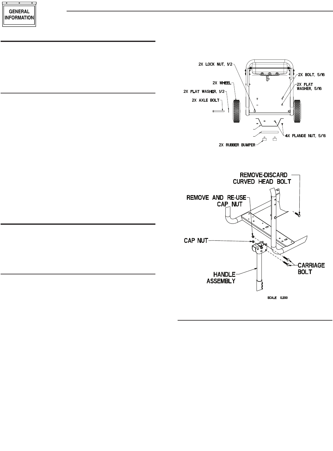
1. Refer to Figure 1 and install Wheels as follows:
• Slide the 1/2” Axle Bolt through the 1/2" Washer, the Wheel
and Wheel bracket on frame.
• Install 1/2” Locking Flange Nuts onto 1/2” Flange Bolt.
2. Refer to Figure 1 and install Frame Foot, Foot Support and
Rubber Feet as shown.
• Slide Rubber Foot stud through the Foot Support and Frame
Foot; Install 5/16” Locking Flange Nuts Slide 5/16” Bolt
through 5/16” Flat Washer and then through holes in Frame
Rail.
• Slide Frame Foot onto 5/16” Bolts; Install 5/16” Locking
Flange Nuts.
3. Refer to Figure 2 and install Handles as shown.
• Remove top Curved Head Bolts and Cap Nuts (Cap Nuts will
be re-used).
• Slide Handle Assembly over Frame Tube, aligning 2 holes.
• Slide 5/16” Carriage Bolts through; Install 5/16” Cap Nuts.
Figure 1 – Wheel Assembly
FOOT SUPPORT
FOOT
Figure 2 – Install Handle Kit
1.2.2 STARTER CONNECTION (ELECTRIC START ONLY)
The unit has been deliberately shipped with the starter cable
disconnected.
To connect starter:
1. Locate starter cable (a hang tag is attached as shown in
Figure 3).
2. Pull vinyl boot back onto starter cable.
3. Remove nut and washer from starter post.
4. Put starter cable onto post and re-install washer and nut.
Section 1 – General Information
Portable Generator System


