


RAPTOR
•
15
their
model at distances farther than a football field (300+ feet). At
greater distances, you could lose sight of your model and you may
also exceed the radio system’s operating range which will cause the
fail-safe system to activate. For best visibility and control of your
model keep your model within 200 feet, regardless of the maximum
range available.
No matter how fast or far you drive your model, always leave
adequate space between you, the model, and others. Never drive
directly toward yourself or others.
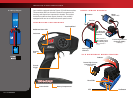
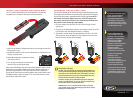
TQ 2.4GHz Binding Instructions
For proper operation, the transmitter and receiver must be electronically
‘bound.’ This has been done for you at the factory. Should you ever
need to re-bind the system or bind to an additional transmitter or
receiver, follow these instructions. Note: the receiver must be connected
to a 4.8-6.0v (nominal) power source for binding and the transmitter and
receiver must be within 5 feet of each other.
1. Press and hold the SET button on the transmitter.
2. Turn on the transmitter and release the SET button. The status LED will
flash red slowly, indicating that the transmitter is in bind mode.
3. Press and hold the LINK button on the receiver.
4. Turn on the speed control by pressing the EZ-Set button and release
the LINK button.
5. When the LEDs on both the transmitter and the receiver turn solid
green, the system is bound and ready for use. Confirm that the
steering and throttle operate properly before driving your model.
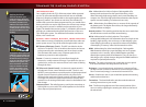
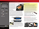
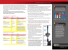
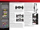
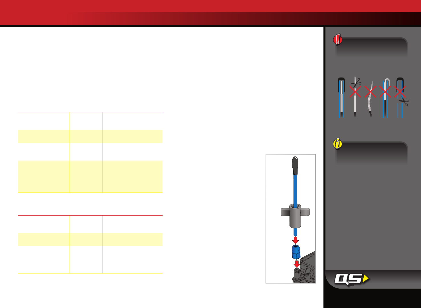
SETTING UP THE ANTENNA
The receiver antenna and antenna tube
must be properly installed before operating
your model. Follow these steps to install the
antenna and antenna tube:
1. Slide the antenna wire into the antenna
tube to its full extent. When fully inserted,
the wire should reach to approximately 1/2
inch below the tube cap. Do not leave any
slack in the antenna wire.
2. Insert the base of the antenna tube into the
antenna post. Take care not to crimp the
antenna wire.
3. Slide the crimp nut over the antenna tube
and screw it onto the antenna post.
4. Use the supplied tool to tighten the crimp
nut on the post just until the antenna tube
is securely in place. Do not overtighten
or crush the antenna wire against the
chassis. Do not bend or kink the antenna
wire! Do not shorten the antenna tube.
See the sidebar for more information.
TRAXXAS TQ 2.4GHz RADIO SYSTEM
Antenna
Tip
Antenna
Tube
Antenna
Wrench
Antenna
Crimp Nut
Antenna
Post
To prevent loss of radio range,
do not kink or cut the black wire,
do not bend or cut the metal tip,
and do not bend or cut the white
wire at the end of the metal tip.
Correct
NoNo NoNo
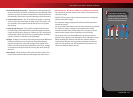
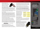
TRANSMITTER LED CODES
LED Color / Pattern Name Notes
Solid green Normal Driving
Mode
See page 13 for information
on how to use the transmitter
controls.
Slow red
(0.5 sec on / 0.5 sec off)
Binding
See this page for more information
on binding.
Flashing medium red
(0.25 sec on / 0.25 sec off)
Low Battery
Alarm
Put new batteries in the
transmitter. See page 11 for
more information.
Flashing fast red
(0.125 sec on / 0.125 sec off)
Link Failure /
Error
Transmitter and receiver are no
longer bound. Turn the system
off and then back on to resume
normal operation. Find source of
the link failure (i.e., out of range,
low batteries, damaged antenna).
RECEIVER LED CODES
LED Color / Pattern Name Notes
Solid green Normal Driving
Mode
See page 13 for information
on how to use your transmitter
controls.
Slow red
(0.5 sec on / 0.5 sec off)
Binding
See this page for more information
on binding.
Flashing fast red
(0.125 sec on / 0.125 sec off)
Fail-Safe / Low-
Voltage Detect
Consistent low voltage in the
receiver triggers Fail Safe so
that there is enough power to
center the throttle servo before it
completely loses power.
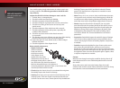
Fail-Safe
Your Traxxas radio system
is equipped with a built-
in fail-safe function that
returns the throttle to its
last saved neutral position
in the event of a signal loss.
The LED on the transmitter
and the receiver will rapidly
flash red when the fail-
safe mode is activated. If
fail-safe activates while you
are operating your model,
determine the reason for
signal loss and resolve the
problem before operating
your model again.
3