


10
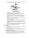
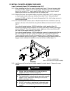
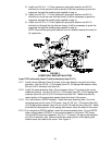
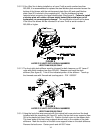
2) Install one 3/8-16 x 1 1/2 hex capscrew, spring disk washer and 3/8-16
whizlock nut to the top front hole as shown (it will be necessary to push the
capscrew through the masking tape applied in step a).
3) Install one 3/8-16 x 1 1/2 hex capscrew, spring disk washer and 3/8-16
whizlock nut to the top rear hole as shown (it will be necessary to push the
capscrew through the masking tape applied in step a).
4) Install one 3/8-16 x 4 1/2 hex capscrew, spring disk washer and 3/8-16
whizlock nut through the top tube as shown (it will be necessary to push the
capscrew through the masking tape applied in step a).
NOTE: Be sure the spring disk washer cone is installed towards the head of
all capscrews.
FIGURE 3
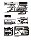
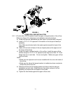
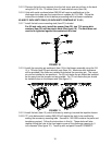
LOWER ROLL BAR INSTALLATION
Lazer Z XP units only (Lazer Z units continue at step 3.2.11)
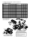
3.2.7 Install mount weldment (Item 9) loosely to the rear bumper using the two holes
provided. Use the 3/8-16 x 1.00 screws (Item 23), 3/8 spring disk washers (Item
25) and 3/8-16 whizlock nuts (Item 24).
3.2.8 Install the frame brackets (Item 16) and spacers (Item 17) loosely to the mount
weldment (Item 9) Use the (2) 3/8-16 x 1.00 screws (Item 23), (2) 3/8 spring disk
washers (Item 25) and (2) 3/8-16 whizlock nuts (Item 24). Make sure that the
raised portion of the spring disk washer faces the head of the screw.
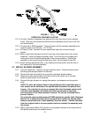
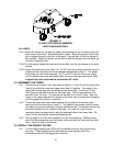
3.2.9 For units without a ROPS installed: Install the frame brackets (Item 16) to the
mounting pads on the Lazer Z XP frame. Use (4) 3/8-16 x 1.00 screws (Item 23),
(4) 3/8 spring disk washers (Item 25 and (4) 3/8-16 whizlock nuts (Item 24). Make
sure that the raised portion of the spring disk washer faces the head of the screw.
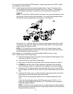
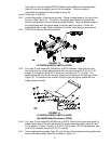
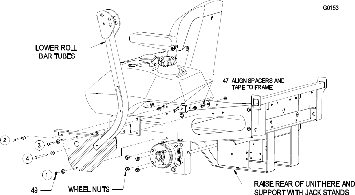
3.2.10 For units with a ROPS installed: Install the frame brackets (Item 16), and ROPS
lower roll bar tubes LOOSELY to the mounting pads on the Lazer Z XP frame.
Use the ROPS mounting hardware, 3/8-16 x 1 ½ screws, 3/8 spring disk washers
and 3/8-16 whizlock nuts. Make sure that the raised portion of the spring disk
washer faces the head of the screw. See Figure 4.