


7
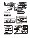
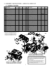
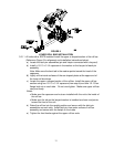
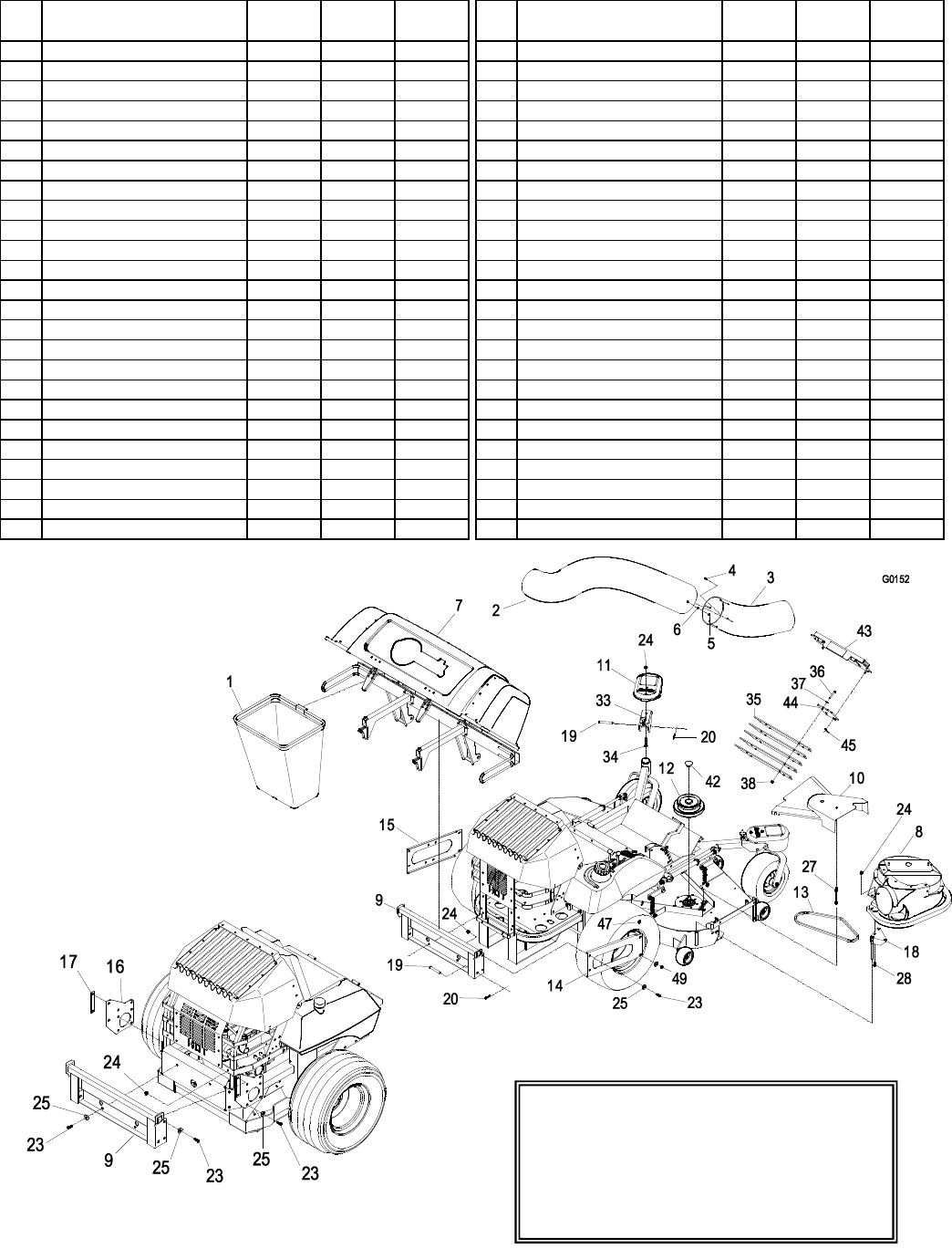
LAZER Z ASSEMBLY DIAGRAM
(Shown without ROPS for clarity)
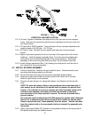
LAZER Z XP ASSEMBLY DIAGRAM
(Shown without ROPS for clarity)
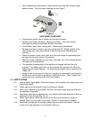
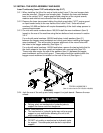
• 52” Lazer Z units with serial numbers below 260,000
require the use of adapter kit 103-1369. Follow the
instructions included in the kit when noted in the
following steps.
• 72” units below serial number 260,000 require the
deck to be modified by adding the accessory
mounting tube. Exmark kit 103-0583 contains the
parts and templates to do this.
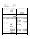
3. ASSEMBLY INSTRUCTIONS – LAZER Z & LAZER Z XP
3.1 ASSEMBLY DIAGRAM
Ref .
No.
Description
Qty
(52 LZ)
Qty
(60&72 LZ)
Qty
(60&72 XP)
1 Bag Assembly 2 3 3
2 Upper Tube 1 1 1
3 Lower Tube 1 1 1
4 #10-24 CRPH Screw 3 6 6
5 #10-24 Nyloc Nut 3 6 6
6 #10 Flat Washer 3 6 6
7 Hood Assembly 1 1 1
8 Blower Assembly 1 1 1
9 Bagger Mount Weldment 1 1 1
10 Belt Cover 1 1 1
11 Caster Weight 2 2 2
12 Jackshaft 1 1 1
13 Blower Drive Belt 1 1 1
14 Frame Bracket RH 1 1
15 Frame Bracket LH 1 1
16 Frame Bracket XP 2
17 XP Mount Spacer 2
18 Mount Pin Weldment 1 1
19 Clevis Pin 4 4 4
20 Hair Pin (large) 4 4 4
21 Chute Pivot Pin 1 1 1
22 Hair Pin (small) 1 1 1
23 3/8-16 x 1.00 Hex Screw 8 8 10
24 3/8 Whizlock Nut 8 11 13
25 3/8 Spring Disk Washer 12 12 14
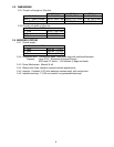
Ref .
No.
Description
Qty
(52 LZ)
Qty
(60&72 LZ)
Qty
(60&72 XP)
26 Blocker Plate (small) 1
27 Belt Shield Stud 1 1
28 3/8-16 x .75 Hex Screw 3 3
29 Belt Cover Spacer 1-60 Only
1-60 Only
30 7/16 Spring Disk Washer
2-60 only
2-60 only
31 Washer – ¼ thick
2 2-60 only
32 3/8-16x3.25 Tap Bolt
2 2-60 only
33 Weight Bracket 2 2 2
34 3/8-16 Square Head Bolt 4 4 4
35 Weight Plate 4 4 4
36 5/16-18 x 1.75 Hex Screw 4 4 4
5/16-18 x 1.5 Hex Screw 4 4 4
37 5/16 Flat Washer 4 4 4
38 5/16-18 Whizlock nut 6 4 4
39 Belt Cover Support 2
40 Knob 1
41 5/16-18 x .75 Hex Screw 2
42 Plug 1 1 1
43 Weight Plate Weldment 1 1
44 Weight Mounting Plate 1 1
45 Hairpin 1 1
46 Drill Template 1 1 1
47 Spacer 6 6 6
48 Plate, Reinforcement 1
49 Nut, Nyloc Thin 2 2 2
Items 21, 22, 26, 29, 30, 31, 32, 46 & 48 not shown.
See figure 1 for installation of 31 & 32.
See figure 4 for installation of 26 & 48.
See figure 5 for installation of 29 & 30.
See figure 9 for installation of 21 & 22.