


- 27 -
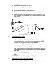
5.1.20 Dielectric grease is used on all blade type electrical
connections to prevent corrosion and loss of contact.
5.2 ADJUSTMENTS
5.2.1 Adjusting cutting height with blade spacers.
Blades may be adjusted for cutting height by using the four 1/4" spacers found
on the blade spindle bolts (factory setting is two above and two below). This
allows a 1" range in 1/4" increments of cutting height in any axle position. The
same number of blade spacers must be used on all blades to achieve a level cut
(two above and two below, one above and three below, etc.).
For the best cut and discharge, place a minimum of two spacers between the
blade and spindle shaft.
For the highest quality cut, place all four spacers between the blade and the
spindle shaft.
If the mulching kit is installed, the highest quality cut can be obtained with 3
spacers between the blade and spindle (minimum is 1 for a good cut).
If you need to cut higher or lower than what the spacers will allow, it will be
necessary to adjust the rear axle height and caster position. See Section 5.2.2
below.
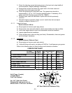
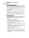
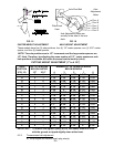
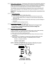
5.2.2 Axle height and caster position.
Desired cutting height range can be obtained by adjusting the rear axle and
placing caster spacers above or below the caster arm (See Figures 15 and 16).
It may be necessary to readjust wheel drive and brake linkages.
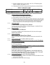
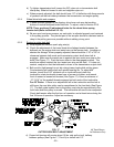
To adjust rear axle:
a) Stop engine and remove spark plug wire(s).
b) Place the drive levers in the neutral lock position.
c) Remove mower deck belt shield for access to axle adjustment belts.
d) Loosen but do not remove the two (2) axle pivot bolts and the two (2) axle
adjustment bolts (See Figure 16).
e) Place a jack under the rear center of the engine deck.
f) Raise the back end of the engine deck up enough to remove the two (2) axle
adjustment bolts.
g) With the jack, raise or lower the back end of the engine deck so that two (2)
axle adjustment bolts can be reinstalled in desired hole location. A tapered
punch can be used to help align the holes.
h) Retighten all four (4) bolts, lower unit and remove jack.
i) Install mower deck belt shield.
j) Adjust wheel drive and brake linkages as required. (See Sections 3.8.5 and
3.8.6).
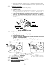
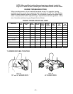
k) Using the appropriate chart for your unit, adjust the caster spacers as
directed to match with the axle hole selected. (See Figure 16) Refer to the
charts and illustrations on the following pages to properly adjust for desired
cutting height.