


- 9 -
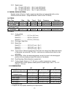
2.11 TORQUE REQUIREMENTS
BOLT LOCATION TORQUE
Blade/Cutter Housing Spindle Bolt ....................................75-80 ft-lbs.
Caster Bracket Mounts......................................................30-35 ft-lbs.
Cutter Deck/Engine Deck Mount.......................................30-35 ft-lbs.
Engine Mounting Bolts
15 & 17 HP Kawasaki & Briggs & Stratton..........15-20 ft-lbs.
Kohler & 12.5 HP Kawasaki................................25-30 ft-lbs.
Transmission Shifter Lever ...............................................30-35 ft-lbs.
3. ASSEMBLY INSTRUCTIONS
3.1 Uncrate unit, leaving it on the pallet, place upper handle assembly, fuel tank, and
shifter lever at the rear of the machine. Place casters at the front of the unit.
3.2 Place a length of 4" x 4" block between the front of the cutter deck and the pallet.
3.3 Remove the bolt bag from the top of the fuel tank support.
3.4 Refer to Parts Manual to help you identify and locate parts and their proper position.
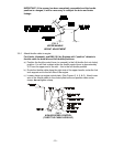
3.5 Install casters to front of deck using appropriate hardware from the bolt bag (eight
3/8 x 3/4" bolts and eight 3/8" whizlock nuts); tightening the lower four bolts first,
then the top four.
3.6 Loosen the 5/16" hardware at the two (2) discharge deflector hinge points so that
the deflector is snug, but can be moved up and down freely.
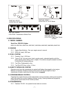
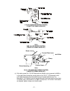
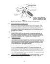
3.7 Mount the fuel tank on the tank support.
Apply retaining adhesive Fel-Pro Pro-Lock ‘Retaining Type I or Retaining II’ or
Loctite RC 609 or 680 on the two threaded studs from the bolt bag and install into
the two left holes underneath fuel tank. Install the fuel tank on top of the fuel tank
support with the studs going through the slots in the support. Install two 5/16 x 3/4
screws with a 5/16” flatwasher and 5/16” lockwasher into the threaded holes in the
right side of the fuel tank.
Do not over tighten
. Place a 5/16” flatwasher, then a
spring, and a 5/16 nyloc nut over each of the studs. Completely tighten nyloc nut
then back off a 1/2 turn. This will allow for normal fuel expansion and contraction
with changes in temperature and fuel levels.
Do not over tighten
.
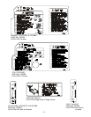
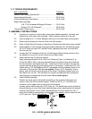
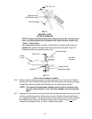
3.8 Install Handle Assembly
Position the lower end of the handle assembly on the outside of the upper rear
section of the fuel tank & handle support. Install one 3/8-16 x 1" bolt (from the
outside in) in the upper hole on each side of the handle.
Loosely secure each screw with a 3/8" nyloc nut. The handle can now be pivoted to
allow positioning in one of the three holes allowing various adjustments for operator
comfort (See Figures 1 & 2). Once a proper position is found, install one 3/8 x 1"
bolt in the bottom mounting holes on each side of the handle. Secure each bolt with
a 3/8" nyloc nut. Tighten all hardware.
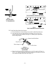
FIG. 1 UPPER HANDLE MOUNTING