


- 12 -
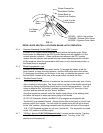
e) Check that the choke adjusting screw just comes in contact with the choke lever
when throttle control is in the full throttle position. (B&S 10.5 hp does not have a
choke adjusting screw.) Choke link should not move when throttle control is
moved to the full throttle position. Be sure choke is fully closed when throttle
lever is moved fully forward to the "CHOKE" position.
f) This step needs to be done after the unit has been assembled and the engine
has been started. Refer to Section 4 (Operation Instructions).
For 12.5 HP Kawasaki, 10.5 HP B&S and Kohler engines:
Check the engine "STOP" position by moving throttle control fully to the rear.
(Note: There is a detent toward the lower end of the slot in the console for
"IDLE", the "STOP" position is rearward from this detent). For Kohler, if engine
continues to run in the "STOP" position, turn kill switch adjusting screw inward
until engine stops, then give it an additional 1/2 to 3/4 turn to assure it will
always function properly.
(12.5 HP Kawasaki and 10.5 HP B&S kill switches are not adjustable).
For 15 & 17 HP Kawasaki engines
:
There is not a “STOP” position. The engine will continue to run when the throttle
control is moved past the rear detent. Turn the ignition switch to the “off”
position to stop the engine.
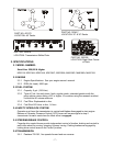
3.8.2 Attach the fuel tank hose to the tank fitting and secure with the clamp provided.
3.8.3 Install the blade engagement linkage to the bell crank on the Left Hand side of the
engine deck. Insert rod through the hole from the outside and fasten with cotter
hairpin.
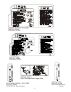
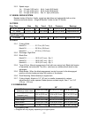
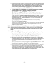
3.8.4 Install and adjust shifter lever.
a) Remove the 3/8" nyloc nut and spring disc washer from the stud on top of the
transmission. Install the shifter lever through slot in shifter lever plate and onto
the stud on top of transmission. Be sure the square-hole washer remains
between the lever and transmission. Replace the spring disc washer and
nyloc nut (See Figure 7). Torque the 3/8" nut to 35 ft. lbs. (47 N⋅m).
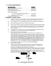
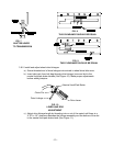
b) Shift lever to second gear and check alignment of lever in slot of shifter plate.
Clearance between top of lever and the top of the slot should be about equal to
the clearance between bottom of the lever and the bottom of the slot (See
Figure 8).
If it is not, remove lever and bend it slightly to adjust.
DO NOT
bend lever while
it is attached to transmission. Reinstall lever and tighten hardware.
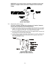
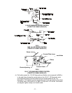
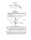
c) Shift to neutral position. Lever should not contact the left edge of the upper slot.
Push lever down. Lever should not contact the right edge of the bottom slot
(See Figure 9). Shifter plate can be adjusted
S
ide to side to adjust position of
lever relative to the slot in plate. Loosen the two bolts securing the shifter plate
to the shifter lever legs. Adjust shifter plate and retighten bolts.