


- 15 -
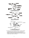
3.8.8 Route the long, unattached wiring harness lead up the left hand side of the handle
and connect the two leads, in any order, to the operator presence control switch
terminals on the inside of the control console. Fasten the lead to the handle with
two large wire ties, from bolt bag, one at the upper end of the handle next to the
console and one at the very lower end of the handle where it attaches to the fuel
tank support.
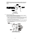
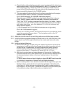
3.9 If the unit is shipped without the muffler attached, install with hardware provided.
For 15 & 17HP Kawasaki units the muffler is installed onto the engine exhaust
manifold but rotated rearward to fit the crate. Loosen the clamp, rotate the muffler
ahead and secure the bracket on the muffler to the bracket on the engine with the
hardware provided. Tighten the clamp.
3.10 Service Engine: Follow the recommendations in the Engine Operators Manual.
3.11
Grease unit.
NOTE: UNIT IS NOT GREASED AT THE FACTORY! Refer to Section 5.1.12 for
locations and grease amounts.
3.12 Follow pre-start instructions as outlined in Section 4.2.
4. OPERATION INSTRUCTIONS
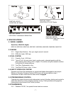
4.1 CONTROLS
4.1.1 Familiarize yourself with the controls and operation of the unit.
Carefully read the following information about the controls and their operation.
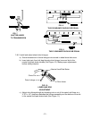
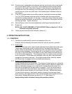
4.1.2 Drive Levers:
Located on each side of the upper handle assembly directly below the handle grips.
These levers individually control clutching action of the wheel drive belts and
brakes. When the drive levers are all the way down, the wheel drive belts engage
and the brakes disengage. Squeezing the left or right hand drive lever causes the
left hand or right hand wheel to slow down or stop, which makes the machine turn
to the left or right respectively. The sharpness of the turn varies by how much the
lever is squeezed. If both levers are squeezed all the way back, both brakes will
engage and the machine will stop. For straight ahead motion, smoothly release
both drive levers to engage both drive wheels simultaneously.
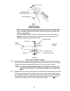
4.1.3 Neutral Lock/Parking Brake Latches:
Located directly above the drive levers. The purpose of these latches is to allow the
operator to lock the drive levers in a "neutral" position where neither the wheel drive
belts nor the brakes engage or in a “park brake” position where the wheel drive
belts are not engaged and the park brake is engaged. To lock the drive levers in
neutral, squeeze the drive levers back, place thumbs on the upper portion of the
neutral lock/park brake latches and move them to the rear. Release drive levers.
To lock the drive levers in “park brake” position, squeeze the drive levers back,
place thumbs on the upper portion of the neutral lock/park brake latches and move
them ahead. Release drive levers as stated in 4.1.2. (See Figure 13).
Apply parking brakes whenever leaving the operators position.