


- 16 -
CAUTION
POTENTIAL HAZARD
♦ If the ignition is in the “ON” position there is potential
for sparks and engagement of components.
WHAT CAN HAPPEN
♦ Sparks could cause an explosion or moving parts
could accidentally engage causing personal injury.
HOW TO AVOID THE HAZARD
♦ Be sure ignition switch is in the “OFF” position before
charging the battery.
3.3.3 Connect the negative battery cables.
NOTE: If the positive cable is also disconnected, connect the positive (red)
cable and the red wire to the positive terminal on the battery first, then connect
the negative (black) cable and white/white wire to the negative terminal on the
battery (red wire and white/white wire are only on some units). Slip insulator
boot over the positive terminal.
NOTE: If time does not permit charging the battery, or if charging equipment is
not available, connect the negative battery cables and run the vehicle
continuously for 20 to 30 minutes to sufficiently charge the battery.
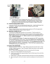
3.4 INSTALL SEAT
a) Remove seat assembly from the crate.
b) Remove the four 5/16-18 whizlock nuts from the seat track studs at the bottom of
the seat. Retain for use later.
c) Align the seat track studs on the bottom of the seat with the holes in the seat
frame. Place seat on top of the frame and secure with the four 5/16-18 whizlock
nuts remove in step b).
d) Connect the wire harness located under the seat on the left side of the mainframe
to the seat switch underneath the seat.
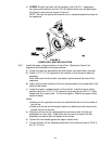
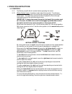
3.5 INSTALL MOTION CONTROL LEVERS.
3.5.1 Loosen and remove the two (2) 3/8” x 1” bolts and spring disc washers which
attach the motion control levers to the control arm shafts for shipping and the
two (2) 3/8” x 1” bolts and spring disc washers which are screwed into the control
arm shafts.
a) Install the left motion control lever onto the control arm shaft (See Figure 4) on
the left side of the console. Place the lever (with the mounting plate towards the
rear) on the outside of the control arm shaft and secure with the bolts and
washers. Position the lever so the bolts are in the center of the slots on the lever
mounting plate and tighten until snug. Repeat on opposite side of unit.
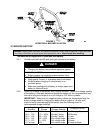
NOTE: There are two lever height options available. Place the levers in the top
two holes to increase height of the levers, or in the bottom two holes to decrease
the height of the levers.
If the levers do not align with each other, when in the neutral position, (See Figure
5) loosen the hardware and make the appropriate adjustment by sliding/tilting the
lever(s) forward or backward until properly aligned and tighten hardware.