


- 13 -
2.10 DIMENSIONS
2.10.1 Overall Width:
without deck deflector up deflector down
60” Deck 54.5 in. (138.4 cm) 61.4 in. (156.0 cm) 72.2 in. (183.4 cm)
72” Deck 58.5 in. (148.6 cm) 73.2 in. (185.9 cm) 84.3 in. (214.1 cm)
2.10.2 Overall Length:
Roll Bar – Up Roll Bar - Down
60” Deck 82.2 in. (208.8 cm) 92.3 in. (234.4 cm)
72” Deck 86.0 in. (218.4 cm) 96.1 in. (244.1 cm)
2.10.3 Overall Height:
Roll Bar - Up Roll Bar - Down
60” Deck 73.7 in. (187.2 cm) 55.6 in. (141.2 cm)
72” Deck 73.7 in. (187.2 cm) 55.6 in. (141.2 cm)
2.10.4 Tread Width: (center to center of tires, widthwise)
Drive Wheels Casters
60” Deck 42.8 in. (108.7 cm) 38.9 in. (98.8 cm)
72” Deck 46.8 in. (118.9 cm) 47.6 in. (120.9 cm)
2.10.5 Wheel Base: (center of caster to center of drive tire)
60” Deck 54.0 in. (137.2 cm)
72” Deck 56.8 in. (144.3 cm)
2.10.6 Curb Weight:
60” Deck 1450 lbs. (658 kg)
72” Deck 1520 lbs. (689 kg)
2.11 TORQUE REQUIREMENTS
Bolt Location
Torque
Cutter Housing Spindle Nut ........................................ 140-145 ft-lbs. (190-197 N-m)
Blade Mounting Bolt.................................................... 115-120 ft-lbs. (156-163 N-M)
Engine Deck/Front Frame Mount Bolts............................... 30-35 ft-lbs. (41-47 N-M)
Anti-Scalp Roller Bolts........................................................ 40-45 ft-lbs. (54-61 N-M)
Engine Mounting Bolts ....................................................... 30-35 ft-lbs. (41-47 N-M)
Wheel Lug Nuts .............................................................. 90-95 ft-lbs. (122-129 N-M)
Wheel Motor Mounting Bolts............................................. 72-77 ft-lbs. (98-104 N-M)
Wheel Hub Slotted Nut ..............................................minimum 125 ft-lbs. (169 N-M)
Rollover Protection System (Roll Bar) Mounting Bolts ....... 30-35 ft-lbs. (41-47 N-M)
3. ASSEMBLY INSTRUCTIONS
3.1 UNCRATE MOWER
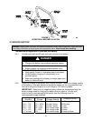
3.2 INSTALL ROLLOVER PROTECTION SYSTEM (ROLL BAR)
3.2.1 Disassemble roll bar from the crate.
a) Remove roll bar tubes from sides of crate.
b) Remove the two brackets used to mount the bottom of the upper roll bar tube
to the crate. Remove the 1/2-13 x 3 1/4 capscrews and 1/2-13 hex flange
lock nuts from the two brackets at each end of the upper roll bar tube and
retain for later use.
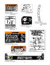
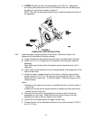
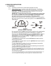
3.2.2 Install the two lower roll bar tubes.
a) Locate the left and right lower roll bar tubes.
b) Align lower roll bar tubes along wheel motor channels as shown in Figure 2.