


Maintenance
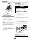
7. Raise the front of the machine and slide the deck
left or right to remove.
8. Lower the front of the machine.
Pump Drive Belt Tension
Self-tensioning - No adjustment necessary.
Deck Belt Tension
Self-tensioning - No adjustment necessary.
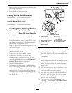
Adjusting the Parking Brake
Service Interval: After the rst 100 hours
Every 500 hours thereafter
Check to make sure brake is adjusted properly.
1. Drive the machine onto a level surface.
2. Disengage the blade control switch (PTO), move
the motion control levers to the neutral locked
position and set the parking brake.
3. Stop the engine, wait for all moving parts to stop,
and remove the key.
4. Raise the back of the machine up and support the
machine with jack stands.
5. Remove the rear tires from the machine.
6. Remove any debris from the brake area.
7. Rotate the drive wheel release handle to the
“released” position. Refer to the Drive Wheel
Release Valves section in Operation.
8. Disengage the park brake.
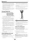
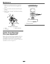
9. Using hands and ngers only, push the caliper
lever arm to engage the brake pads on the rotor
until the lever stops. While holding the lever at the
stopped position, use the other hand or ngers
to pull the cable threaded end tight through the
swivel. Spin the standard nut against the swivel
(see Figure 30).
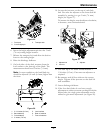
Figure 30
Left Hand Brake Shown
1. Cable anchor
6. Lock nut
2. Threaded rod 7. Pull cable threaded rod
this direction
3. Push lever this direction 8. Hold threaded rod here
4. Caliper lever arm 9. Swivel (pivot head)
5. Standard nut (shown
against swivel)
Note the order of the standard nut and lock nut
(no nut on the cable anchor side of the swivel).
10. Release hold on the caliper lever and cable. The
wheel hub should turn by hand in both directions
relative to the caliper; some friction/resistance
is acceptable.
11. If there is no movement between the hub rotor
and the caliper then back off the standard nut one
turn from the swivel and repeat step 10 (drive
release valves must be in the “released” position
on the hydros).
12. If the hub rotor moves very freely relative to the
caliper, then tighten the standard nut one turn
against the swivel and repeat step 10.
13. Once step 10 is achieved, hold the threaded rod
end with a tool and tighten the lock nut against
the standard nut. Do Not allow the cable to turn
when the nuts are tightened.
14. Rotate the drive wheel release handle to the
“operating” position. Refer to the Drive Wheel
Release Valves section in Operation.
15. Repeat on the opposite side of machine.
39