


Operation
Deck Lift Pedal
Located at the right front corner of the oor pan.
Push the pedal forward with your foot to raise the
cutting deck. Allow the pedal to move rearward to
lower the cutting deck to the cut height that has been
set.
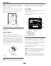
Transport Lock
Located on the height of cut adjustment plates to the
right of the parking brake.
Position in the transport latching position to
automatically latch the cutting deck when raised to
the transport position (see item 1 in Figure 11).
In the non-latching position, the deck will
automatically return to the cutting height when the
pedal is lowered (see item 3 in Figure 11).
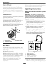
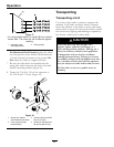
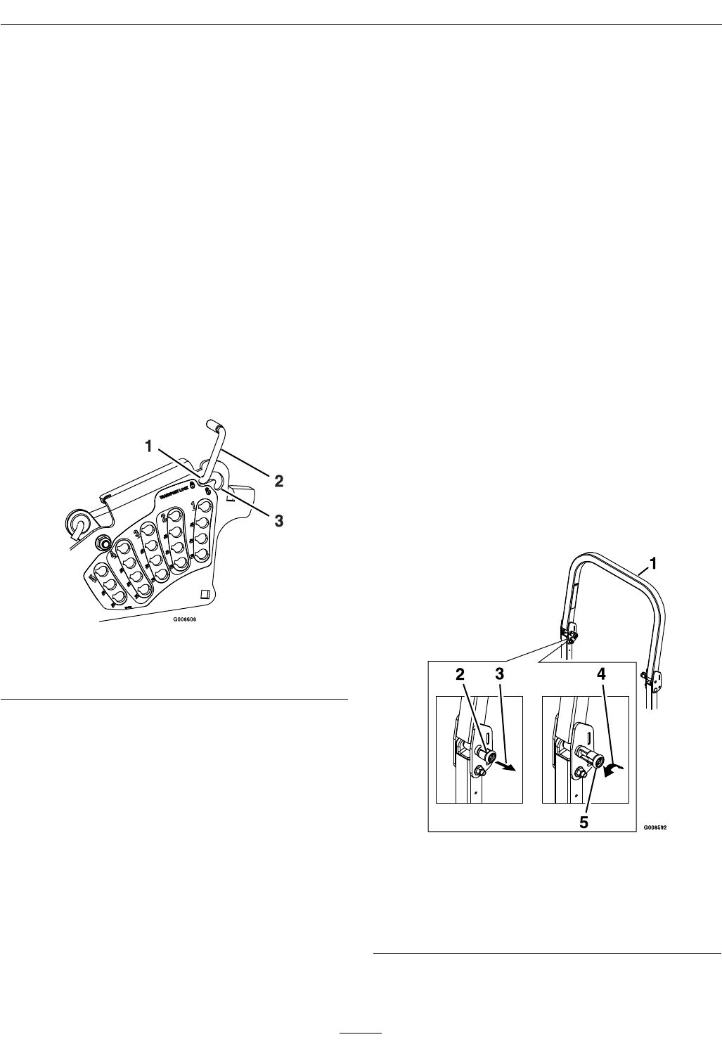
Figure 11
1. Latching position 3. Non-latching position
2. Transport lock control
Pre-Start
Fill fuel tank. For best results use only clean, fresh
regular grade unleaded gasoline with an octane rating
of 87 or higher.
Do Not add oil to gasoline.
Do Not overll fuel tank. Never ll the fuel tank so
that the fuel level rises above a level that is 1/2 inch
(13 mm) below the bottom of the ller neck to allow
for fuel expansion and prevent fuel spillage.
Make sure you understand the controls, their
locations, their functions, and their safety
requirements.
Refer to the Maintenance section and perform all the
necessary inspection and maintenance steps.
Operating Instructions
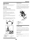
Raise the Rollover Protection System
(ROPS)
Important: The roll bar is an integral and
effective safety device. Keep the roll bar in the
raised and locked position when operating the
mower. Lower the roll bar temporarily only when
absolutely necessary.
1. The knob must be completely latched with the
tabs interlocking as shown in Figure 12 to lock
the roll bar in the raised, operate position.
2. Apply forward pressure to the upper hoop of the
roll bar.
3. Pull the knob and rotate 90° to hold in the
unlatched position to lower the roll bar.
4. To return to the operate position, raise the roll
bar, and then rotate knobs 90° so that the tabs
interlock partially. Apply forward pressure to the
roll bar upper hoop and observe that the knobs
return to the completely latched position.
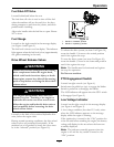
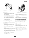
Figure 12
1. Roll bar upper hoop
2. Knob in “latched” position
3. Pull knob to unlatch
4. Rotate 90° to hold unlatched
5. Knob in “unlatched” position
5. Make sure the knobs are fully engaged with the
roll bar in the raised position. The upper hoop of
22