


Maintenance
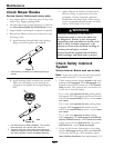
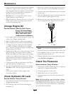
3. If any breaks in the screen or welds are observed,
replace arrester.
4. If plugging of the screen is observed, remove
arrester and shake loose particles out of the
arrester and clean screen with a wire brush (soak
in solvent if necessary). Reinstall arrester on
exhaust outlet.
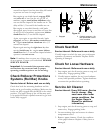
Thread Locking Adhesives
Thread locking adhesives such as “Loctite 242”
or “Fel-Pro, Pro-Lock Nut Type” are used on the
following fasteners:
• ROPS spring pin housing.
• Hydro pump control arm, linkage bolt, and
attachment bolt.
• Hydro cooling fan screw.
• Hydro park brake cable anchor mounting bolt
• Sheave and clutch retaining bolt in the end of
engine crankshaft.
Thread locking adhesives are required for some
hardware on engines — see the Engine manual.
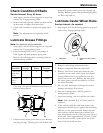
Copper-Based Anti-seize
Copper-based anti-seize is used in the following
location:
On threads of Blade Bolts. See Check Mower
Blades section.
Dielectric Grease
Dielectric grease is used on all blade type electrical
connections to prevent corrosion and loss of contact.
Adjustments
Note: Disengage PTO, shut off engine, wait for
all moving parts to stop, engage parking brake, and
remove key before servicing, cleaning, or making any
adjustments to the unit.
CAUTION
Raising the mower deck for service or
maintenance relying solely on mechanical
or hydraulic jacks could be dangerous. The
mechanical or hydraulic jacks may not be
enough support or may malfunction allowing
the unit to fall, which could cause injury.
Do Not rely solely on mechanical or hydraulic
jacks for support. Use adequate jack stands
or equivalent support.
Deck Leveling
1. Position the mower on a at surface.
2. Stop engine, wait for all moving parts to stop, and
remove key. Engage parking brake.
3. Check the tire pressure in the drive tires. Proper
ination pressure for tires is 13 psi (90 kPa).
Adjust if necessary.
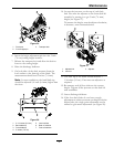
4. Position the transport lock in the latching
position.
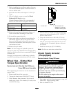
5. Push the foot pedal all the way forward and the
deck will latch at the 5 1/2 inch (14 cm) transport
position (Figure 25).
36