


Maintenance
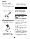
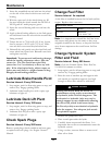
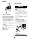
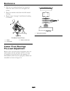
Figure 28
1. Single point height adjustment bolt
2. Front height-of-cut plate mounting bolt
3. Rear height-of-cut plate mounting bolt
15. To adjust the single point system, rst loosen the
front and rear height-of-cut plate mounting bolts.
16. If the deck is too low, tighten the single point
adjustment bolt by rotating it clockwise. If
the deck is too high, loosen the single point
adjustment bolt by rotating it counterclockwise.
Note: Loosen or tighten the single point
adjustment bolt enough to move the height-of-cut
plate mounting bolts at least 1/3 the length of
the available travel in their slots. This will regain
some up and down adjustment on each of the
four deck links.
17. Re-tighten front and rear height-of-cut plate
mounting bolts.
Important: Torque the front and rear
height-of-cut plate mounting bolts to 27-33
ft-lb (37-45 N-m).
18. Repeat steps 9 through 13.
Deck Removal
Before servicing or removing the deck, the spring
loaded deck arms must be locked out.
WARNING
Deck lift arm assemblies have stored energy.
Removing the deck with out releasing the
stored energy can cause serious injury or
death.
Do Not attempt to disassemble the deck
from the front frame without locking out the
stored energy.
1. Stop engine, wait for all moving parts to stop, and
remove key. Engage parking brake.
2. Remove the height adjustment pin and lower the
deck to the ground.
3. Place the height adjustment pin in the 3 inch (7.6
cm) cutting height location. This locks the deck
lift arms in the lowest position when the deck is
removed.
4. Remove the oorpan and belt shields.
5. Insert 1/2 inch socket driver into the square hole
on the idler bracket and carefully rotate the deck
idler counterclockwise to remove the belt.
6. Remove and retain the hardware on both sides of
the deck as shown in Figure 29.
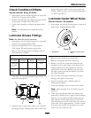
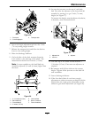
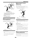
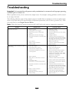
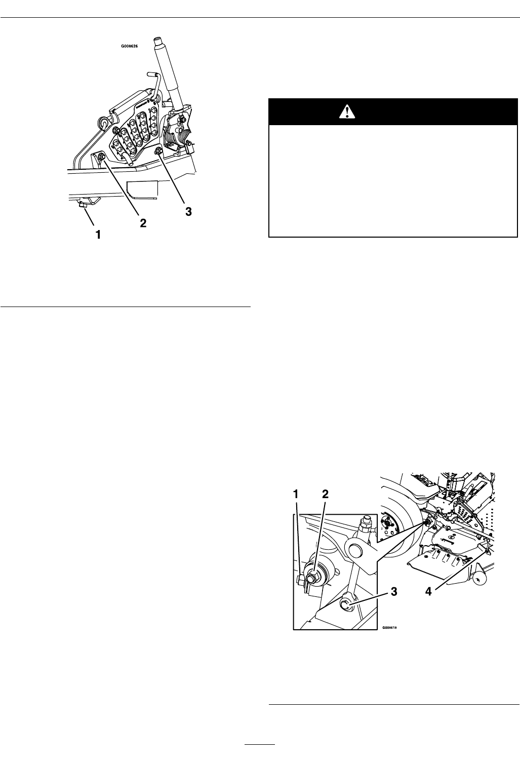
Figure 29
1. Panhard rod (right side only)
2. Deck strut
3. Rear deck lift attachment shoulder bolt and nut.
4. Front deck lift attachment shoulder bolt and nut.
38