


Maintenance
a steady ow of oil to ow out from under the
housing. Retighten the capscrews. Do this for
both pumps.
Note: Hydraulic reservoir can be pressurized up
to 5 psi to speed this process.
6. If either drive wheel still does not rotate, stop
and repeat steps 4 and 5 above for the respective
pump. If wheels rotate slowly, the system may
prime after additional running. Check oil level
as stated in Check the Hydraulic Oil Level
section.
7. Allow unit to run several minutes after the charge
pumps are “primed” with drive system in the full
speed position. Check oil level as stated in Check
the Hydraulic Oil Level section.
8. Check hydro drive linkage adjustment as stated in
Hydro Drive Linkage Adjustment section in
Adjustments.
Wheel Hub-Slotted Nut
Torque Specication
Service Interval: After the rst 100 hours
Every 500 hours thereafter
When tightening the slotted nut on the wheel motor
tapered shaft:
1. Torque the slotted nut to 100 ft-lb (136 N-m).
2. Further tighten the nut until the next set of slots
line up with the cross hole in the shaft.
3. Replace cotter pin.
Note: Do not use anti-seize compound on the wheel
hub.
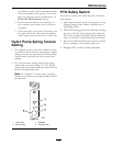
Inspect PTO Clutching Belt
Tension
Service Interval: After the rst 2 hours
Check every 2 hours
for the rst 8 hours of
operation.
Every 40 hours thereafter.
1. Stop engine and wait for all moving parts to stop.
2. Engage PTO lever.
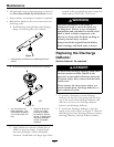
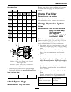
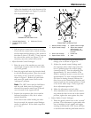
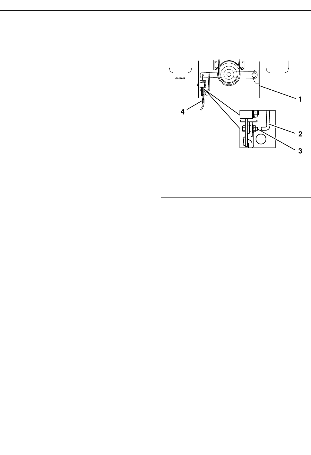
3. Look through the round hole in the left rear
corner of the engine deck to inspect blade
clutching belt tension. Bolt on blade engagement
linkage bellcrank and indicator arm should align
within 1/16 inch (1.6 mm) (see Figure 14). Refer
to PTO Engagement Linkage for adjustment.
Figure 14
1. Engine deck 3. Align bolt to indicator
within 1/16 inch (1.6
mm)
2. Indicator 4. Turnbuckle
Thread Locking Adhesives
Thread locking adhesives such as “Loctite 242”
or “Fel-Pro, Pro-Lock Nut Type” are used on the
following fasteners:
• Pump sheave setscrews.
• Square head setscrews on hydro pump control
arms.
• OPC lever setscrews.
• Lower sheave retaining bolt on clutch arm.
• Shoulder bolts in ends of speed control crank.
• Sheave retaining bolt in end of engine crankshaft.
• Fuel tank bulkhead tting threads
Adhesives such as “Loctite RC/609 or RC/680” or
“Fel-Pro Pro-Lock Retaining I or Retaining II” are
used on the following:
• OPC lever hubs and cross-shaft.
Note: Care must be used not to bond the
bearing, next to each OPC hub, to the cross-shaft
which could cause binding of the OPC levers and
erratic operation.
• Fuel tank studs, where studs are inserted into tank.
31