


Maintenance
2. Lift deck and secure in raised position as stated in
the Clean Grass Build-Up Under Deck section.
3. Inspect blades and sharpen or replace as required.
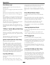
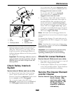
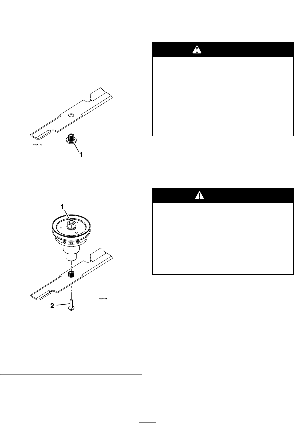
4. Reinstall the blades (if they were removed) in the
following order:
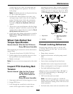
A. Install bushing through blade with bushing
ange on bottom (grass) side of blade.
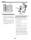
Figure 10
1. Install bushing in blade prior to installing bushing in
spindle.
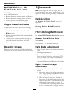
B. Install bushing/blade assembly into spindle.
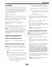
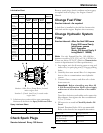
Figure 11
1. Use wrench here for
blade installation. This
nut has been torqued to
140–145 ft-lb (190–197
N-m)
2. Torque to 55-60 ft-lb
(75-81 N-m) Apply
lubricant to threads
as needed to prevent
seizing. Copper-based
anti-seize preferable.
Grease acceptable
substitute.
C. Apply lubricant to threads of blade bolt as
needed to prevent seizing. Copper-based
anti-seize preferable. Grease acceptable
substitute. Install blade bolt nger tight. Place
wrench on the top spindle nut then torque the
blade bolts to 55-60 ft-lb (75-81 N-m).
WARNING
Incorrect installation of the blade or
components used to retain the blade can
be dangerous. Failure to use all original
components and assembled as shown could
allow a blade or blade component to be
thrown out from under the deck resulting in
serious personal injury or death.
Always install the original Exmark blades,
blade bushings, and blade bolts as shown.
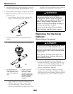
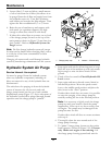
Replacing the Discharge
Deector
Service Interval: As required
DANGER
An uncovered discharge opening could allow
the lawn mower to throw objects in the
operator’s or bystander’s direction and result
in serious injury. Also, contact with the blade
could occur.
Never operate the lawn mower unless you
install a mulch plate, discharge deector, or
grass collection system.
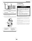
1. To remove a damaged or worn discharge
deector, lift the leg of the spring with the loop
out of the notch in the discharge deector and
slide the rod out of the discharge deector
brackets, and discharge deector.
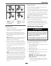
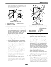
2. To install new discharge deector, orient the
spring on the rod as shown in Figure 12. Slide the
rod through the front discharge deector bracket,
discharge deector, and rear deector bracket.
26