


Operation
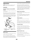
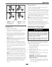
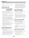
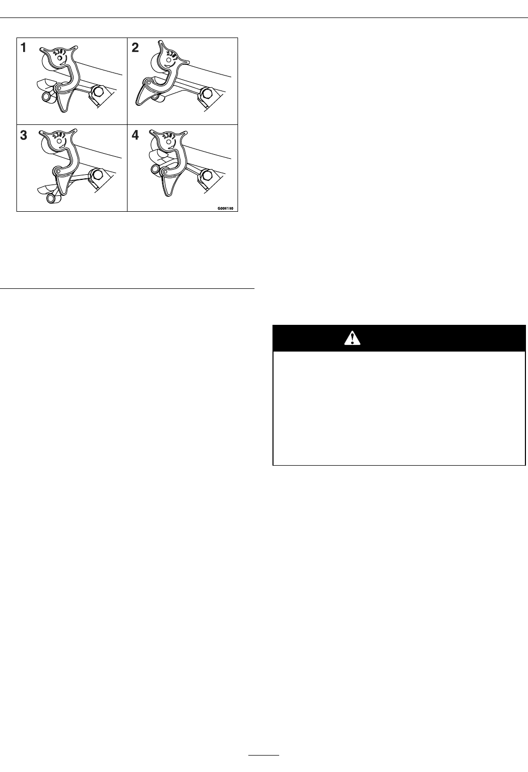
Figure 5
1. Drive Lever in neutral
position
3. Drive Lever in forward
position
2. Drive Lever locked in
neutral position
4. Drive Lever in reverse
position
Driving Forward
1. Release the parking brake.
2. With drive levers locked in “neutral”, shift speed
control lever to desired forward speed.
3. Slowly squeeze and hold both drive levers in
the neutral position and rotate both neutral lock
latches from the neutral lock position to the
forward position.
Note: Do Not squeeze both drive levers all the
way back. This will cause the drive wheels to
engage in the reverse direction.
4. To move forward in a straight line, smoothly
release both drive levers to engage drive wheels.
To turn left or right, squeeze the right hand drive
lever to turn right and the left hand drive lever
to turn left.
To make a “zero turn”, squeeze either the left
hand or the right hand drive lever back into the
reverse position while the opposite drive lever is in
a forward position at an equal but opposite speed.
Note: For smooth operation of this machine,
avoid quick, jerky movements of the drive levers.
Move the drive levers smoothly and deliberately.
To stop, squeeze drive levers back to the “neutral”
position. Move the neutral lock latches into the
“neutral lock” position and release drive levers.
Move the speed control lever to the neutral
position.
Driving in Reverse
To move rearward in a straight line, squeeze drive
levers into the reverse position.
To turn left or right, squeeze the right hand drive lever
to turn left and the left hand drive lever to turn right.
To make a “zero turn”, squeeze either the left hand
or the right hand drive lever back into the reverse
position while the opposite drive lever is in a forward
position at an equal but opposite speed.
Note: For smooth operation of this machine, avoid
quick, jerky movements of the drive levers. Move the
drive levers smoothly and deliberately.
To stop, squeeze drive levers back to the “neutral”
position. Move the neutral lock latches into the
“neutral lock” position and release drive levers. Move
the speed control lever to the neutral position.
Adjusting the Cutting Height
WARNING
When the two front support rod hairpins are
removed from the mower deck, the weight of
the tractor section may cause the front frame
of the unit to rise suddenly. If the unit rises
suddenly, injury may occur.
Securely hold down the front of the unit when
the front support rod hairpins are removed.
The cutting height of the mower deck is adjusted
from 1 1/2 to 4 1/2 inches (3.81 cm to 11.4 cm) in
1/2 inch (1.3 cm) increments.
1. Stop the machine and move the drive levers to the
neutral locked position.
2. Disengage the PTO.
3. Engage the park brake.
4. Stop the engine, remove the key and wait for all
moving parts to stop.
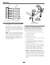
5. Install hairpin clips in the holes for the desired
cutting height. See Figure 6.
Important: To maintain correct cutting
height and rake, check the following for
proper adjustment.
A. The front and rear hairpins are in the same
holes with the proper spacers under the hair
pins. See Figure 6.
21