


Operation
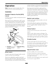
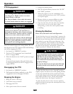
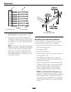
Figure 6
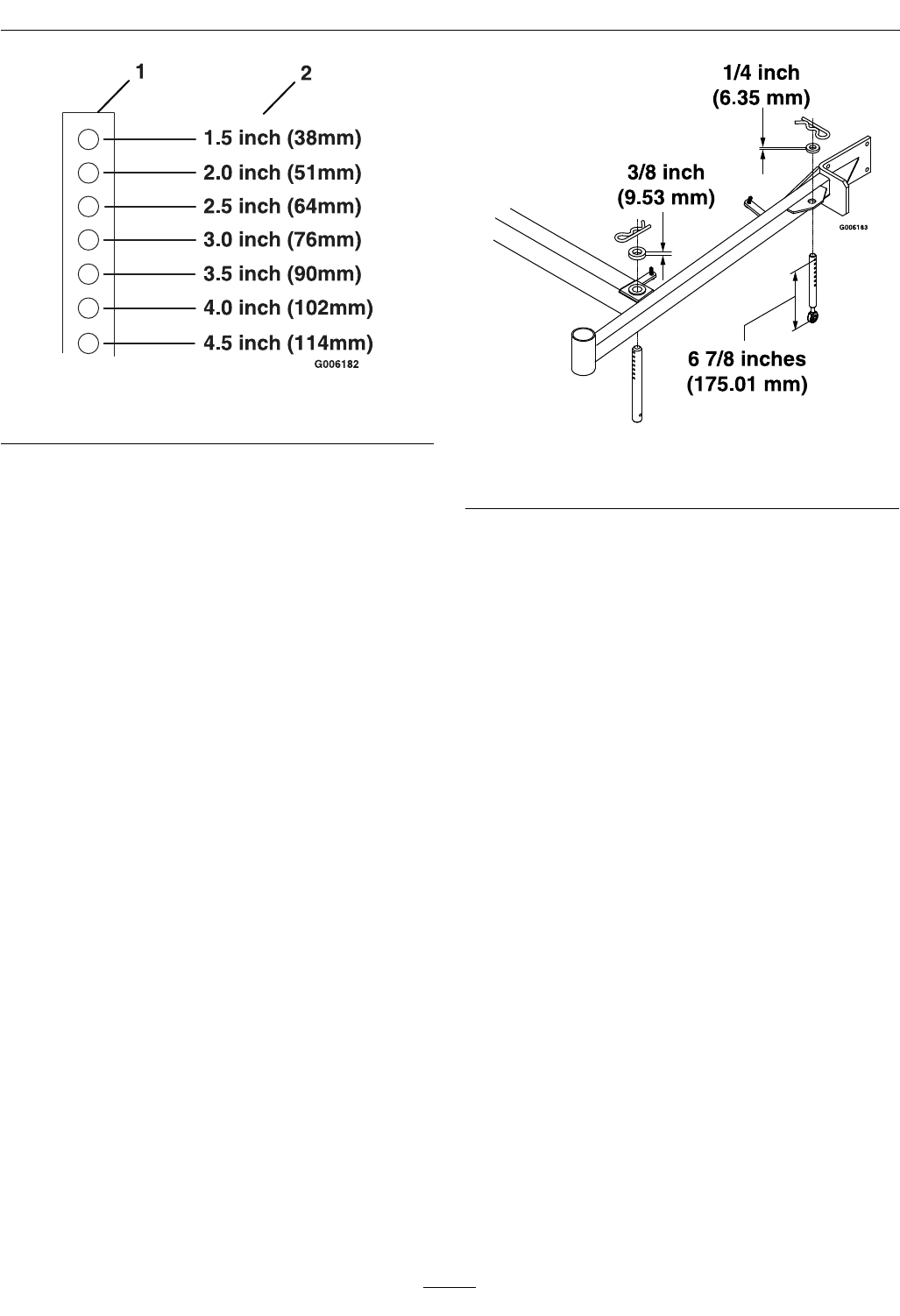
1. Deck support pin
2. Cutting Height
B. The tire pressures are set as directed in Check
Tire Pressures in the Maintenance section.
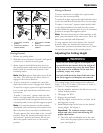
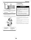
C. The length of the rear deck support link
assemblies average 6.89 inches (approximately
6 7/8 inches) (175.01 mm) from the center of
the balljoint to the center of the farthest hole.
See Figure 7.
Note: All four pins must equally support the
weight of the deck. Adjustment in the length
of the rear deck support assemblies may be
necessary. If one side is longer than 6.89
inches (approximately 6 7/8 inches) (175.01
mm), than the opposite side must be shorter
by the same amount.
Figure 7
Left Hand Side Shown
Adjusting the Anti-Scalp Rollers
It is recommended to change the anti-scalp roller
position when the height of cut has changed.
1. Stop the machine and move the drive levers to
the neutral lock position.
2. Disengage the PTO.
3. Engage the park brake.
4. Stop the engine, remove the key and wait for all
moving parts to stop.
5. After adjusting the height of cut, adjust the
anti-scalp rollers by removing the whizlock nut
and spring disc washer.
6. Adjust anti-scalp rollers for Normal Operating
Conditions. Place rollers in one of the positions
shown in Figure 8. Rollers will maintain 3/4
inches (19 mm) clearance to the ground to
minimize gouging and roller wear or damage.
Note: For Maximum Deck Flotation, place
rollers one hole position lower. Rollers should
maintain 1/4 inch (6.35 mm) clearance to ground.
Do Not adjust rollers to support the deck. Be
sure roller bolts are installed with the spring disc
washer between head of the nut and mounting
bracket.
22