Maintenance
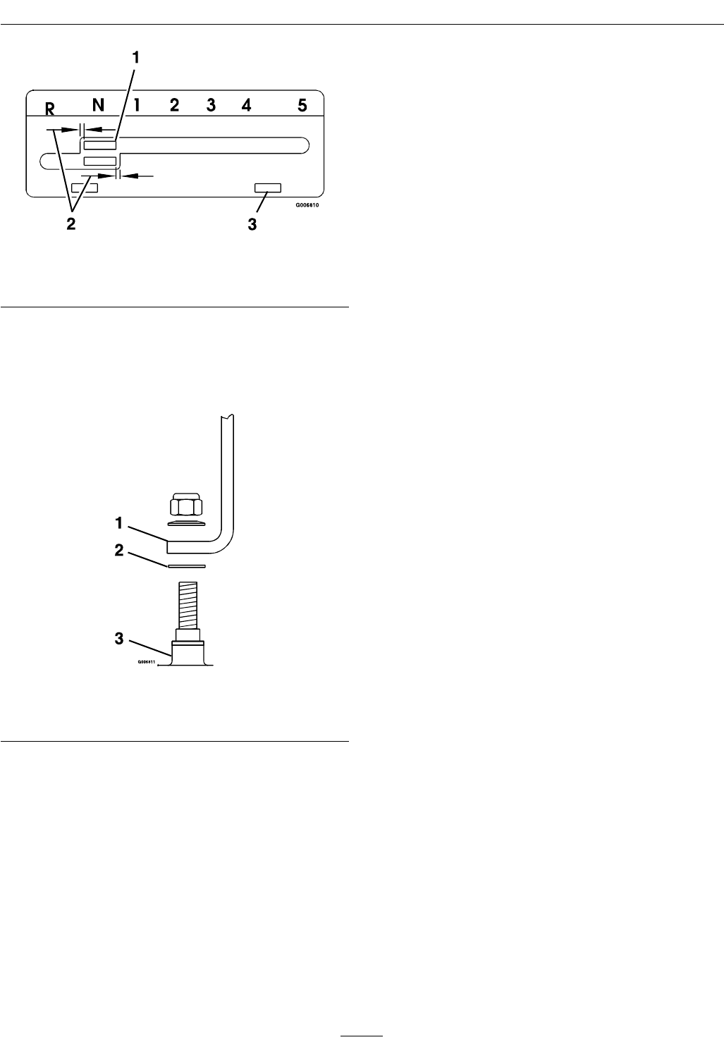
Figure 24
1. Shifter Lever
3. Adjustment slot
2. Equal distance
• To adjust the shifter lever:
1. Remove the 3/8 inch nyloc nut and spring
disc washer from the stud on top of the
transmission (See Figure 25).
Figure 25
1. Shifter Lever
3. Transmission
2. Square Holed Washer
2. Remove the shifter lever and bend it slightly.
Do Not bend the lever while it is attached to
the transmission.
3. Re-install lever and torque the 3/8 inch nyloc
nut to 35 ft-lb (47 N-m).
• To adjust shifter plate:
Note: The square-hole washer must be between the
lever and the transmission.
Place shifter lever in the neutral position. Loosen the
two bolts securing the shifter plate to the shifter lever
legs. Adjust shifter plate and retighten bolts.
Shifter Detent Adjustment
Transmission shifter detent can be adjusted
by adjusting the setscrew on the back side of
transmission located just behind the neutral start
switch. Turn setscrew in (clockwise) to hold the
transmission shifter more positively in each gear and
to increase the force on the lever required to shift
gears.
Turn setscrew out (counterclockwise) to decrease
force on lever required to shift gears. Factory setting
is to turn setscrew all the way in then back out 1 1/2
turns.
Important: Screwing setscrew in too far will
prevent the transmission from shifting.
PTO Safety Switch
Adjustment
1. Stop engine and wait for all moving parts to stop.
Engage parking brake. Remove key or spark plug
wire(s).
2. With the blades disengaged and the bellcrank
touching the engine deck, adjust the blade safety
switch (if needed) until the bellcrank depresses
the plunger by 1/4 inch (.64 cm).
3. Be sure the bellcrank does not contact the switch
body to prevent damage to the switch.
4. Retighten switch mounting hardware.
Handle Height Adjustment
The handle can be pivoted to allow positioning in
one of the three holes allowing various adjustments
for operator comfort (see Figure 26).
To adjust the handle height:
1. Remove the bottom mounting hardware on each
side of the handle.
2. Pivot the handle to one of the three positions.
3. Re-install hardware and tighten.
Important: If the handle height position is
changed, it will be necessary to readjust the
drive and brake linkage (see Check Brake and
Wheel Drive Linkage Adjustment section in
Operation.)
32


