


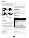
Maintenance
Cutting Height Adjustment Table (1 inch to 4 1/4 inches (2.5 cm-10.8 cm)) (cont'd.)
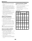
Number Of Spacers
Below Caster
Support Hub
Number of 1/4 inch Blade Spacers Below Spindle
Cutting
Height
Range
Axle
Position
(Figure 10)
1/2
inch
3/16
inch
4
3 2
1 0
3 1/8–
4 1/8 inches
(7.9–10.5 cm) E 4 0
3 1/8 inch
(7.9 cm)
3 3/8 inch
(8.6 cm)
3 5/8 inch
(9.2 cm)
3 7/8 inch
(9.8 cm)
4 1/8 inch
(10.5 cm)
3 1/4–
4 1/4 inches
(8.3–10.8 cm) E 4 1
3 1/4 inch
(8.3 cm)
3 1/2 inch
(8.9 cm)
3 3/4 inch
(9.5 cm)
4 inch
(10.1 cm)
4 1/4 inch
(10.8 cm)
Important: Always adjust the Number of Spacers below Caster Hub to correspond to the Axle
Position as shown in table to obtain proper “rake” (blades should always be level to the ground
or tipped slightly down at the front).
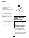
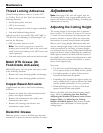
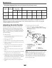
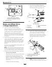
Adjusting the Axle Position
Desired cutting height range can be obtained by
adjusting the rear axle and placing caster spacers
above or below the caster arm (See Figure 10 and
Figure 11 along with the Cutting Height Adjustment
Chart). It may be necessary to readjust wheel drive
and brake linkages.
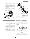
To adjust rear axle:
1. Stop the machine and move the drive levers to
the neutral lock position.
2. Disengage the PTO.
3. Place the drive levers in the neutral lock position.
4. Remove mower deck belt shield for access to axle
adjustment bolts.
5. Loosen but do not remove the two axle pivot
bolts and the two axle adjustment bolts (see
Figure 10).
6. Place a jack under the rear center of the engine
deck.
7. Raise the back end of the engine deck up enough
to remove the two axle adjustment bolts.
8. With the jack, raise or lower the back end of the
engine deck so that two axle adjustment bolts can
be reinstalled in desired hole location. A tapered
punch can be used to help align the holes.
9. Retighten all four bolts, lower unit and remove
jack.
10. Install mower deck belt shield.
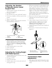
11. Adjust wheel drive and brake linkages as
required (see Brake and Wheel Drive Linkage
Adjustment section).
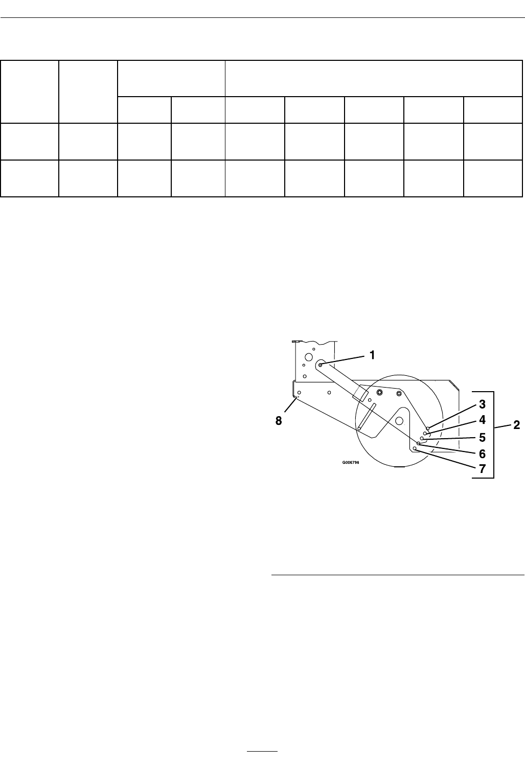
Figure 10
1. Axle Pivot Bolt
5. Position C
2. Axle Adjustment Holes
(Located in the side of
the rear deck.)
6. Position D
3. Position A 7. Position E
4. Position B 8. Place jack here
Note: The axle positions are in 1/2 inch (1.3 cm)
increments and the large caster spacers are 1/2
inch (1.3 cm) thick. Therefore, by adjusting the
same number of 1/2 inch (1.3 cm) caster spacers as
axle hole positions the blades will retain the same
front-to-back tip (rake).
26