


Maintenance
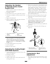
a slight upward force placed on the drive
levers to remove any "slack" in the linkage.
C. Re-install hairpin into hole on the clevis
pin between the neutral lock/park brake
latch and drive lever (See Figure 19).
Repeat procedure on opposite side of unit.
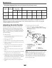
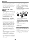
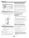
• For ECS Handles:
Allow drive levers to drop into the full forward
position: the at edge of the drive lever
should align with the bottom roller notch (See
Figure 21). Adjust if necessary
Figure 21
1. Notch in Neutral
Lock/Park Brake Latch
2. Drive Lever
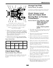
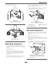
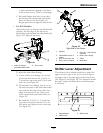
To adjust the wheel drive linkage:
A. Locate a drive lever linkage on one side
of the unit and remove the 5/16-18 x 1
3/4 inch hex cap screw and 5/16-18 inch
nyloc nut (see Figure 22).
B. Thread drive lever linkage into or out of
the swivel located on the wheel drive idler
arm until the at edge of the drive lever
aligns with bottom of the roller notch
in the neutral lock/park brake latch (see
Figure 22).
C. Re-install the 5/16-18 x 1 3/4 inch hex
cap screw and secure with the 5/16-18
inch nyloc nut. Repeat for the other side
(see Figure 22).
Figure 22
Right Side of Unit Shown
1. Wingnut
5. 5/16–18 x 1 3/4 inch hex
capscrew
2. Transmission Lever in
neutral
6. Drive Lever Linkage
3. 5/16–18 inch nyloc nut 7. Swivel
4. Drive Levers in neutral 8. Brake Rod
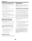
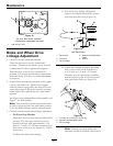
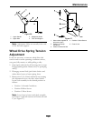
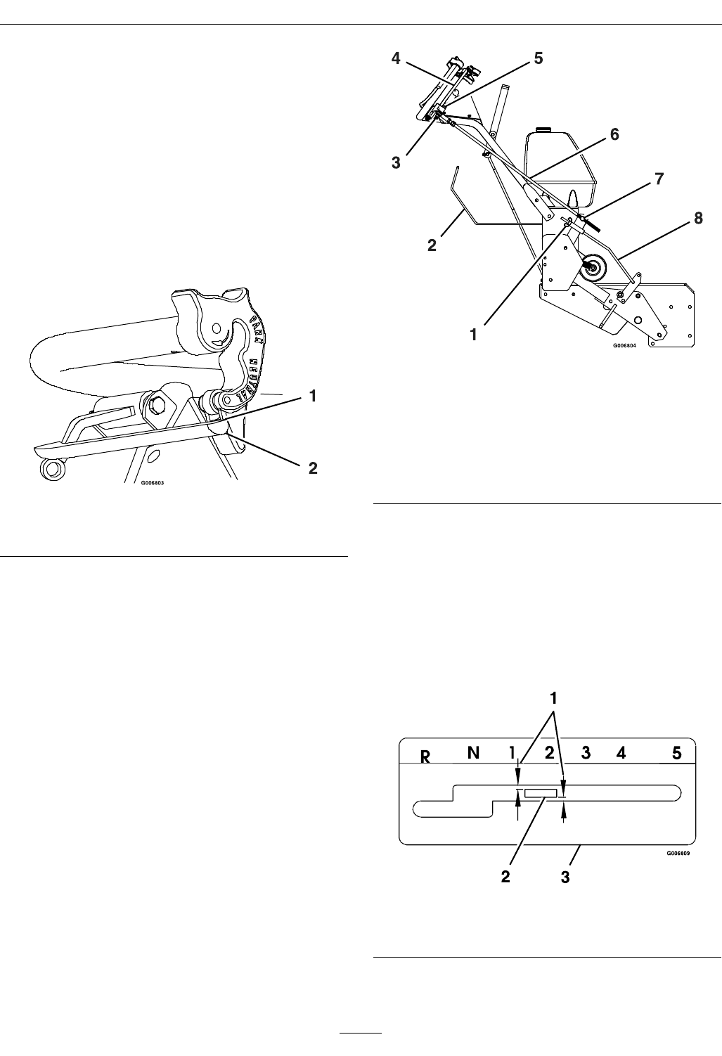
Shifter Lever Adjustment
The shifter lever in neutral should not contact the
upper or lower edge of the slot or the left edge of
the upper slot or the right edge of the bottom slot
(See Figure 23 and Figure 24). The clearance should
be equal. Adjust the shifter lever and shifter plate
if necessary.
Figure 23
1. Equal distance
3. Shifter Plate
2. Shifter Lever
31