


11
CS-400
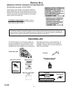
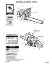
PREPARATION FOR USE
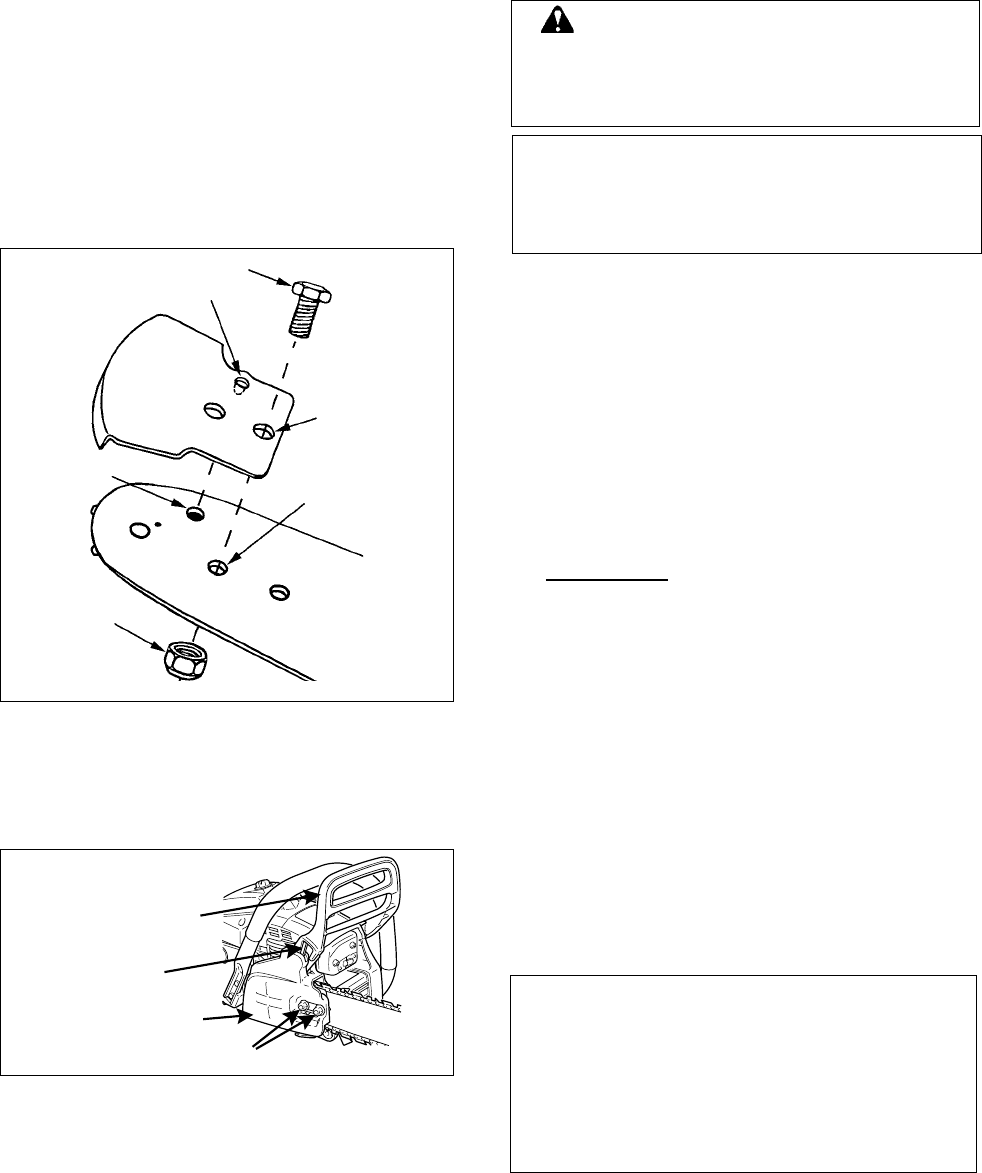
Bolt (A)
Dimple (D)
Recess (E)
Front hole (C)
Rear hole (B)
Nut (F)
Guide bar
Kick Guard
®
Brake connector
Clutch cover
Brake lever
(Front hand guard)
Two nuts
WARNING
Saw chain is sharp! Always wear gloves
when handling assembly, otherwise serious
personal injury may result.
NOTE
The machine may be delivered with guide bar,
tip guard, and saw chain separated. Install guide
bar, tip guard, and saw chain as follows.
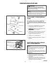
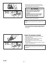
KICK GUARD
®
TO BAR INSTRUC-
TIONS
Tools Needed: Two 11 mm (7/16 in.) Wrenches.
For saws with Kick Guard
®
P/N 2893201 and
Symmetrical Low-Kick type (Double Guard) guide
bars.
1. Install bolt (A) in rear hole (B) of Kick Guard
®
and through front hole (C) in guide bar.
2. IMPORTANT: Dimple (D) in Kick Guard
®
must
engage recess (E) in guide bar.
3. Tighten nut (F) and bolt (A) using 11 mm (7/16
in.) wrenches until snug. Make certain Kick
Guard
®
is ush against guide bar.
4. Tighten nut (F) 1/8 additional turn.
5. Check to make certain Kick Guard
®
is tight on
guide bar.
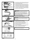
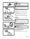
GUIDE BAR AND SAW CHAIN IN-
STALLATION/REMOVAL
NOTE
• Move the chain brake lever (Front hand guard)
fully rearward to remove or install the clutch
cover to chain saw.
• Align the brake connector of the clutch cover to
the groove on the side of the brake lever (Front
hand guard).
1. Remove spark plug lead. (See page 27)
2. Remove two clutch cover nuts and remove
clutch cover.
3. Remove bar and saw chain if necessary. See
“Maintenance and Care” section for guide bar/
saw chain maintenance procedures.