


2
A&E CATALINA 2500
A&E CATALINA 2500
INSTALLATION/OPERATION
APPLICATION
The A&E Catalina 2500 Case Awning is designed and
intended for direct mounting on straight and most curved
mini-motorhomes, pick-up campers, vans, van conversions
and pop-up tent trailers.
The optional Universal Van Adapter Kit, A&E Part No.
930035 allows permanent or temporary mounting to vans
with rain gutters without drilling holes in the van.
Important: Read the entire installation procedure
before starting installation.
Note: The Dometic Corporation assumes no liability for
damages or injuries resulting from installation or operation
of this product.
The Dometic Corporation reserves the right to modify
appearances and specifications without notice.
INSTALLATION
Tools Required:
o Measuring Tape o Pencil
o Electric Drill o Pop Rivet Gun (Necessary
o Drill Bits #& or 3/6, 1/8 only if Backing Plate is
o Center Punch needed)
o Phillips Screw Driver o Silicone Sealant
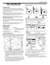
For Direct Wall Mounting:
Note: When determining location for awning make sure to
consider door clearance, if required, and location of other
vehicle components like compartment doors, mirrors, etc..
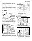
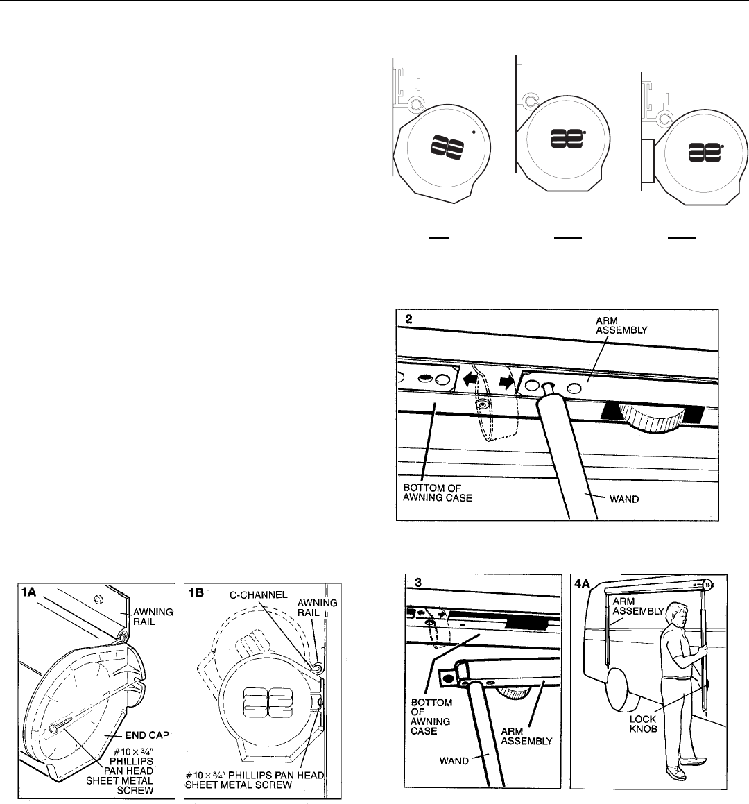
1. A. Install C-Channel of awning case into awning rail by
inserting C-Channel into one end of awning rail and
sliding awning case into position (FIG. 1A), or by
tilting case up and inserting entire C-Channel into
awning rail and rotating case down into position
(FIG. 1B).
B. Using the end caps as templates, drill one 1/8 Dia.
hole into vehicle for each end cap (FIG. 1A). Secure
each end cap using one #10 x 3/4 Phillips pan head
sheet metal screw with a small dab of silicone
sealant on each screw (FIG 1A & 1B).
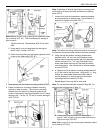
NO YES
Shim not supplied
YES
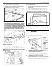
Note: Awning must be mounted with case back parallel to
side wall of vehicle.
Note: Be sure to use a dab of silicone sealant on every
screw where a hole has been drilled in the side of the
vehicle. This will prevent possible water leakage.
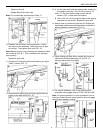
2. Using the wand, open awning case by inserting the pin
on the end of the wand into hole in arm assembly
indicated by arrows on bottom of case (FIG. 2)
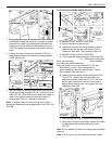
3. Lower arm assembly out of awning case (FIG. 3)
4. A. Allow arm to hang freely from case. Tighten lock
knob (FIG. 4A). Repeat for other side.
Note: For curved sided vehicles proceed to Step 4B. For
straight sided vehicles skip to Step 5.
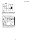
B. Lower arm assembly to ground. With foot still on
ground raise inner arm as high as it will go (FIG. 4B).