


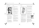
Riser rail
Part the mounting bracket
assembly so that the fixing plate
is separate from the cover.
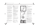
Establish the best position for the
riser rail, and mark the wall for
the lower mounting bracket.
Make allowances for the tallest person likely to
use the shower regularly.
When drilling through tiles use a
suitable glass or tile drill of 6mm
diameter to drill through the tile
only. Use a no 10/5.5mm masonry
drill to make a hole 35mm deep,
and fit the wall plug. (NB some
wall constructions may require the use of
different types of wall fixings to those supplied).
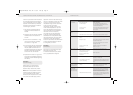
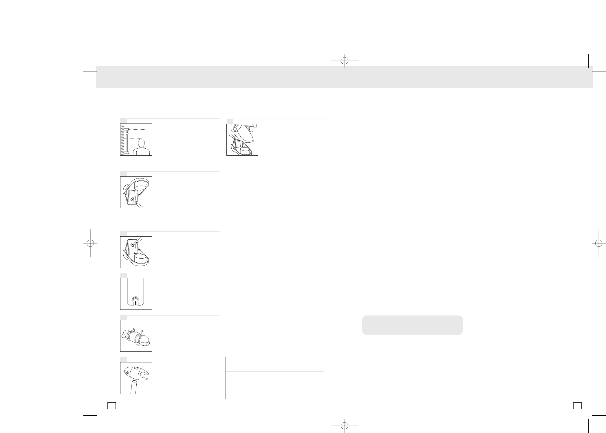
Screw the lower bracket base to the wall.
Locate the crimped end of
the riser rail (Figure 4) into the
mounting bracket, then fit
the upper bracket to the rail.
Ensure the rail is vertical, then
mark the wall for the fixing.
NOTE if it is necessary to
shorten the rail, use a junior
hacksaw to cut the excess
material from the plain end
of the rail (the uncrimped
end).
Insert the end pieces of the
height adjuster into the body
section matching the letters A
and B (moulded into the ends
of each piece) and twist so the
pieces lock together.
With the shower head holder in
the upright position (widest
opening at the top) and the
lever in the open position, slide
the assembly onto the rail.
Tighten the height adjuster to
the rail by twisting the lever.
Insert the rail into the bottom
and top brackets and screw
the upper mounting bracket
in place. Clip the end caps
onto the mounting brackets.
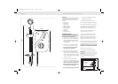
Electrical
Switch off the water supply at the isolating
valve before connecting the wiring to the
unit.
The shower unit must be permanently
connected to the electricity supply, direct
from the consumer unit via a double pole
linked switch with a minimum contact gap
of 3mm.
It is recommended that the switch be a
cord operated type with neon on/off
indicator, otherwise the switch should be
readily accessible, clearly identifiable and
out of reach of any person using the shower.
The wiring to the switch must be done
without the use of a plug or socket outlet.
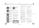
The cable used must be of a diameter
suitable for the power rating of the
shower selected. The table below may
be used as a guide to the cable
requirements. If in doubt consult a
qualified electrician.
kW rating Minimum Fuse rating Max cable length
Isolating switch (Amps) (Amps) Consumer unit to
shower (m)
6mm cable 10mm cable
7.5 40 40 27 44
8.5 40 40 23 38
9.5 40 40 21 32
10.5 45 45 18 30
2
3
4
5
6
1
7
INSTALLATION INSTALLATION / FINAL ASSEMBLY AND COMMISSIONING
The cable should be routed to the shower
unit from either the top, bottom or back
of the shower unit. This cable should be
hidden from view.
Connect the brown live wire to the terminal
marked L
Connect the blue neutral wire to the terminal
marked N
Connect the yellow and green earth
wire to the terminal marked E on the
backplate.
IMPORTANT – ensure the terminal block
screws are fully tightened and that no
insulation enters the terminal block,
preventing a good electrical connection.
To conform to IEE regulations the earth
continuity conductor of the electrical
installation must be effectively connected
to all exposed metal parts of other
appliances and services in the room in
which the shower unit is installed.
WARNING! Do not attempt to operate
the shower unit until the installation is
fully complete.
SECTION 3
Final assembly and commissioning
With the unit wired and plumbed correctly
the front cover may now be refitted.
1) Place the cover lightly over the shower
unit and turn the knobs so that they
engage correctly with the spindles.
The front cover may then be pressed
lightly into place and secured using the
two fixing screws.
2) Fit the flexible hose to the shower unit
and remove the showerhead.
3) Turn the temperature control knob at
the bottom of the unit fully
anti-clockwise.
4) Turn on the power at the isolating
switch.
5) Start the shower by pressing the cold
power selector button. The water
should now begin to flow through the
shower.
Warning do not attempt to select any other
setting other than Cold at this stage.
6) Once a steady stream of water is
achieved from the outlet of the shower
unit stop the shower by pressing the
STOP button.
7) Pass the hose through the hole in the
soap dish and refit the shower head.
8) Fit the handset into the height adjuster
and clip the soap dish onto the riser
rail.
The unit is now ready for commissioning.
Commissioning the shower
Important: The shower unit must be full of
water before power (heat) settings are used.
1) With the water supply to the unit turned
on, turn the bottom temperature
control knob anti-clockwise to the full
cold position. No water should exit the
shower either from the handset or from
any other part of the shower unit.
6 7
Dimp13292-Shower inst aX4 5/5/04 2:08 pm Page 7