


Rev: 8/2008
17 of 21
36B, 36BX, 36H, 36HX, 52H, 52HX
DEK
®
is exclusively distributed by GXi International, LLC
Heavy Duty Power Equipment
Service Adjustments
WARNING
DANGER: Before making any adjustments and/or servicing your
lawn mower, make sure the lawn mower is on level ground,
blades disengaged, key removed, and the engine off with the
spark plug wire(s) removed from the spark plug(s) to prevent ac-
cidental contact. If adjustments or maintenance is being per-
formed after operation of the lawn mower, allow the unit to cool
since heat build up could cause severe burns.
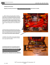
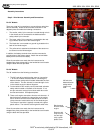
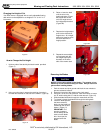
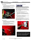
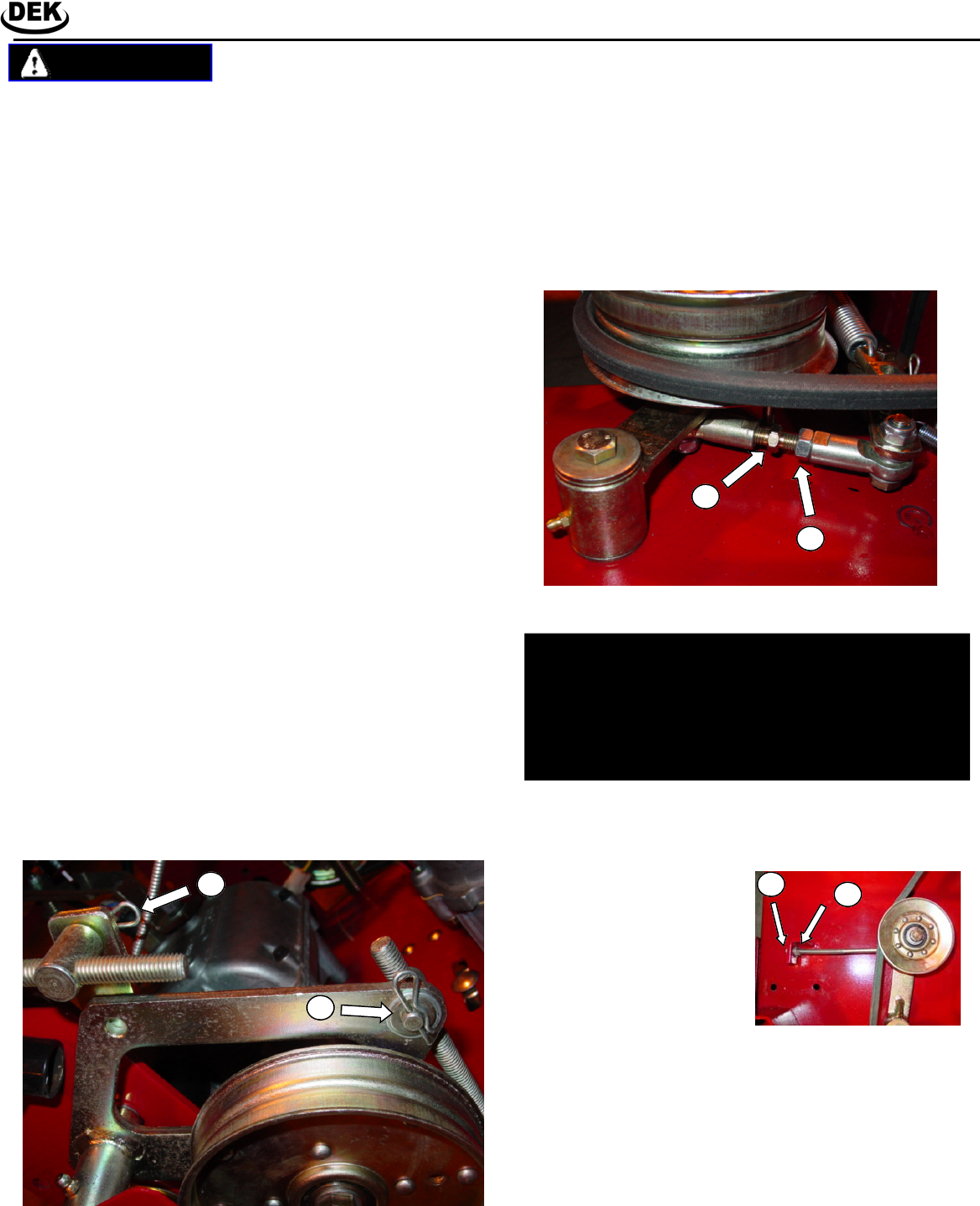
Drive Belt and Brake Adjustment, 36B and BX Models:
Engine to Blade Belt Adjustment:
1. Remove the deck cover and move the blade control lever
on the control console to the “ON” position.
2. With approximately 10 lbs of pressure being applied on
the engine to blade belt midway between with pulleys,
the belt should move approximately ½”.
3. If the belt moves more than ½”, move the blade control
lever back to the “OFF” position.
4. Loosen locking nut “X”.
5. Rotate turnbuckle “Y” until desired tension is achieved.
6. Tighten locking nut “A” when finished
7. Replace deck cover.
Figure 15
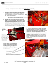
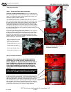
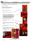
52” Blade to Blade Belt Adjustment:
1. Remove the deck cover.
2. With approximately 10
lbs of pressure being
applied on the blade to
blade belt, midway be-
tween the pulleys, the
belt should move ap-
proximately ½”.
3. If the belt moves more
than ½”, Loosen locking
nut “M” and turn nut “N”
clockwise approximately
1-2 turn.
4. Recheck the tension on the blade to blade belt. If it is
still loose repeat step 3. Important: Do not over tighten
the blade to blade belt. Over tension can cause prema-
ture wear on belts and blade spindles.
5. Re-tighten locking nut “M.”
6. Replace deck cover.
Figure 16
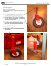
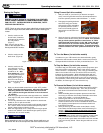
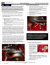
To adjust the actuation of the brake and the drive belt, there are
two adjustable “swivels” attached to threaded rods in the belt /
clutch / brake assembly.
The objectives of fine tuning the adjustment are to:
1. Equalize the “feel” and action between pistol grips on each
side of the mower.
2. Achieve desired belt slippage with approximately 50% to 75%
travel of the handle bar grips.
3. Achieve brake activation during the last 50% travel of the han-
dle grips.
4. Achieve locked brakes when the handle bar grips are locked in
the “parking brake position.”
The upper swivel adjusts primarily the belt slippage on the pulley.
To adjust the belt slippage, place the mower in 1st gear and move
until locked in gear. Remove the retaining pin (A) and the washer.
Pull the swivel out of the hole. Rotate the swivel in the desired
direction on the threaded rod to achieve the desired feel and mo-
tion. Place the swivel back into the hole. Reconnect the pin and
washer. Test the belt slippage action of the controls by squeezing
the pistol grip lever. Continue adjusting until you have achieve the
desired feel. Once complete with one side, perform the identical
adjustments to the other side.
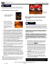
To adjust the brake activation, start by releasing the parking brake
and leave the handle bar grip in a neutral position. Remove retain-
ing clip (B) and washer. Rotate the swivel in the desired direction
on the threaded rod to achieve the desired brake activation position
and feel. Place the swivel back into the hole. Reconnect the pin
and washer. Test the belt slippage action of the controls by
squeezing the pistol grip lever. Continue adjusting until you have
achieve the desired feel. Once complete with one side, perform
the identical adjustments to the other side.
A
B
X
Y
M
N
IMPORTANT! The mower belts are adjusted to ensure
the blades stop turning within 7 seconds of releasing the
blade control lever. If you are making any belt adjust-
ments whatsoever, for your safety and the safety of oth-
ers around you, you must ensure the belts are re-
adjusted to achieve this design specification.