


Rev: 8/2008
10 of 21
36B, 36BX, 36H, 36HX, 52H, 52HX
DEK
®
is exclusively distributed by GXi International, LLC
Heavy Duty Power Equipment
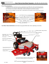
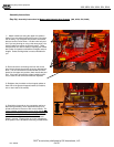
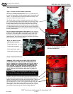
For 52” Models
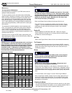
There are a total of 4 connections to connect the pre-wired han-
dle bar assembly. Route the wire harness as shown on the
adjacent photo and make the following connections:
1. The smaller, white, 2-pin connector is routed through a hole
in the chassis and is connected to the blade activation
safety switch 2-pin connector.
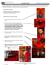
2. The larger, white, 5-pin connector is connected to the mat-
ing connector at the rear of the Honda engine.
3. The black wire is connected to a ground lug located on the
back of the Honda engine.
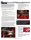
4. The yellow wire is attached to the bottom of the starter mo-
tor solenoid on the Honda engine.
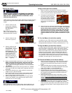
In addition, the battery terminal wires must be connected to
provide power to the electric starter. Attach the red and black
battery terminal wires to the battery.
Once all connections are made, the wire harness can be
strapped into place permanently to the handle bars and chassis
using the black wire-ties provided.
For 36” Models
The 36” models have the following connections:
1. The 36” hydro drive model has the same as “connection
1” for the 52” models discussed above, connecting the
blade activation safety switch located underneath the front
of the chassis. The wire harness is routed through a hole
in the chassis as per the above diagrams.
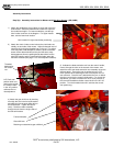
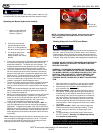
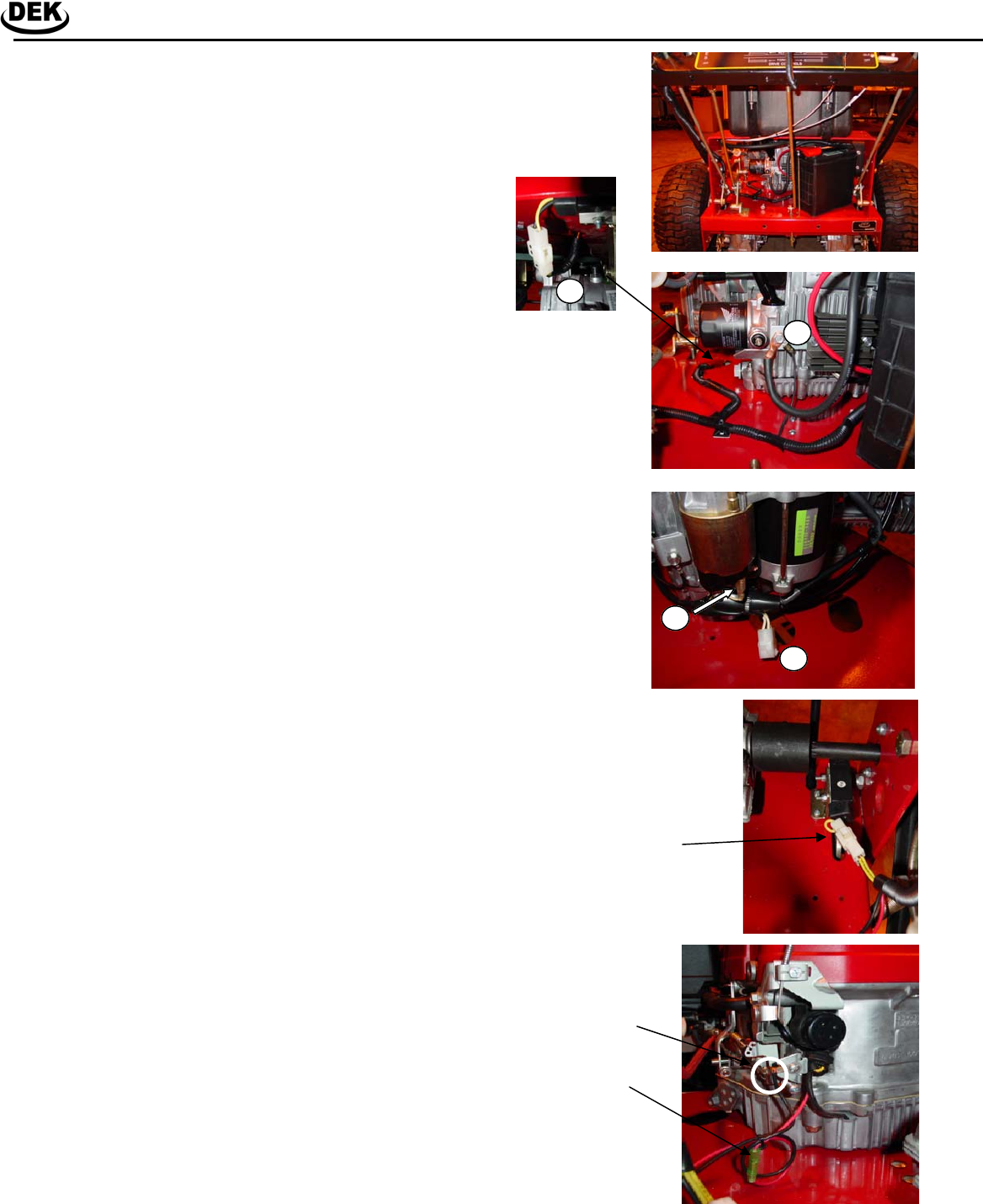
2. For the belt drive 36” models, connect the blade activation
safety switch located on the back of the chassis. It is a
two pin connector coming from a black switch box under
the fuel tank bracket. See adjacent photo.
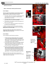
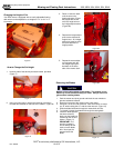
3. There are 2 engine connections from the wire harness. A
black wire that is attached to a ground lug on the engine
and a red wire connector that is attached to the red wire
crimp connector located at the rear of the Honda engine.
The crimp on connector is typically covered with a green
plastic sleeve. The red wire is the engine kill switch wire.
Once all connections are made, the wire harness can be
strapped into place permanently to the handle bars and chassis
using the black wire-ties provided.
Assembly Instructions
Step 3: Wire Harness Assembly and Connections
1
2
3
4
36” belt drive
blade activation
safety switch
location top
view.
Black ground
wire for Honda
engine.
Red wire with
crimp connec-
tors and typi-
cally a green
plastic cover.