


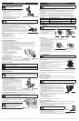

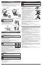

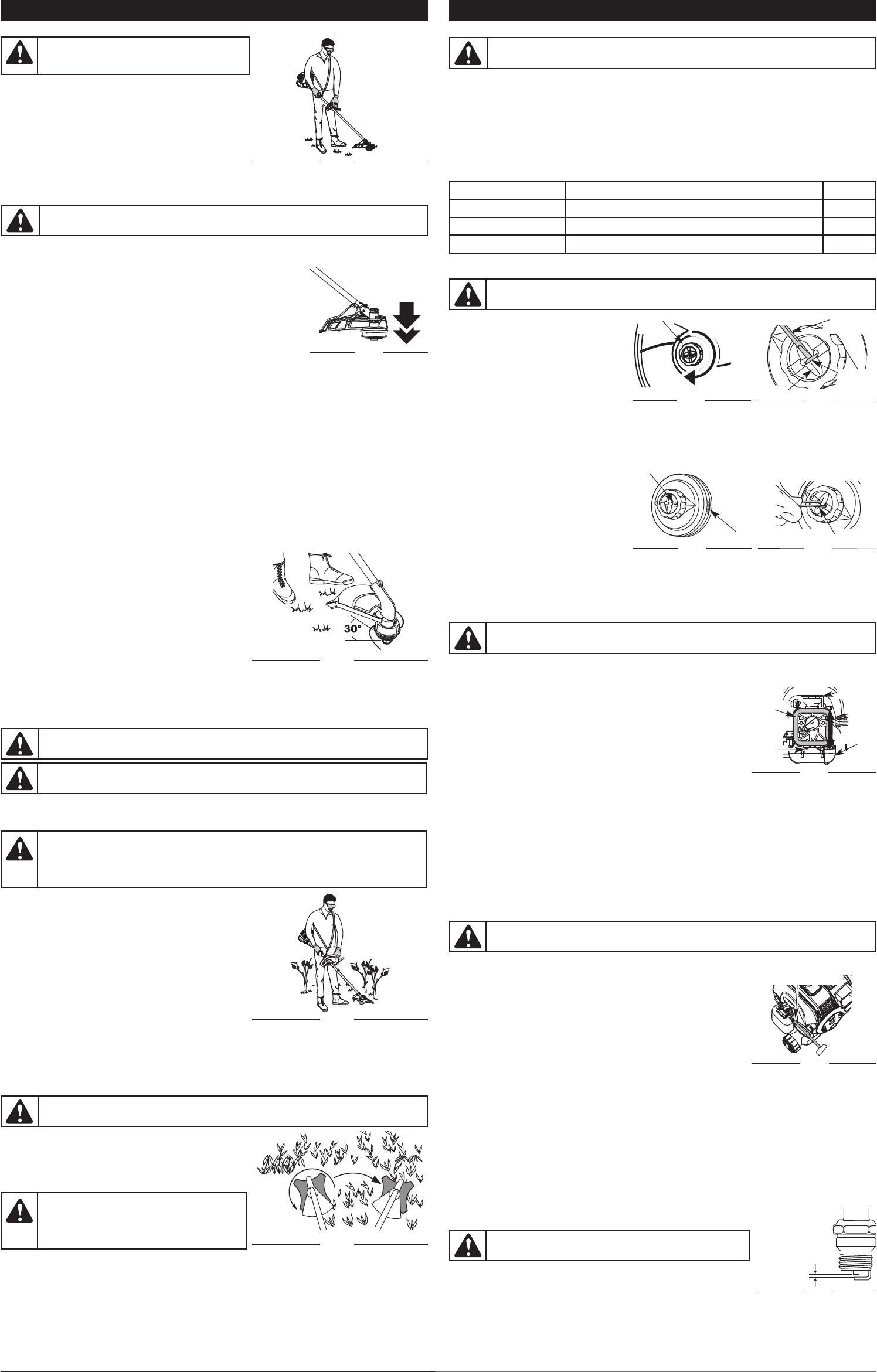
REMOVING THE LINE
1. Rotate the bump knob clockwise until all line is
inside the cutting head (Fig. 28).
2. Using a flat-head screwdriver, insert the tip into
t
he line dimple and just under the exposed
portion of the line (Fig. 29)
3. Pull the line straight out until all line is removed
f
rom the cutting head.
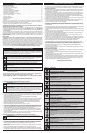
5
MAINTENANCE AND REPAIR INSTRUCTIONS
WARNING: Never use metal-reinforced line, wire, chain or rope. These can break off and
become dangerous projectiles.
MAINTENANCE SCHEDULE
Perform these required maintenance procedures at the frequency stated in the table. These procedures
should also be a part of any seasonal tune-up.
NOTE: Some maintenance procedures may require special tools or skills. If you are unsure about these
procedures take your unit to any non-road engine repair establishment, individual or authorized
service dealer.
NOTE: Maintenance, replacement, or repair of the emission control devices and system may be
performed by any non-road engine repair establishment, individual or authorized service dealer.
NOTE: Please read the California/EPA statement that came with the unit for a complete listing of terms
and coverage for the emissions control devices, such as the spark arrestor, muffler, carburetor, etc.
W
ARNING:
T
o prevent serious injury, never perform maintenance or repairs with unit running. Always
service and repair a cool unit. Disconnect the spark plug wire to ensure that the unit cannot start.
FREQUENCY MAINTENANCE REQUIRED SEE
Before starting engine Fill fuel tank with fresh fuel p. 4
Every 10 hours Clean and re-oil air filter p. 5
Every 25 hours Check spark plug condition and gap p. 5
F
lat-Head
Screw Driver
Trimmer
L
ine
D
imple
B
ump
K
nob
Fig. 29
F
ig. 28
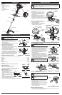
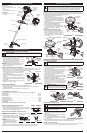
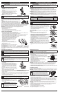
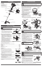
OPERATING INSTRUCTIONS
HOLDING THE UNIT
Before operating the unit, stand in the operating position
(Fig. 23). Check for the following:
• The operator is wearing eye protection and proper clothing
• With a slightly-bent right arm, the operator’s hand is
holding the shaft grip
• The operator’s left arm is straight, the left hand holding
the D-handle
• The unit is at waist level
• The cutting head is parallel to the ground and easily
contacts the grass without the need to bend over
ADJUSTING TRIMMING LINE LENGTH
The Bump Head™ cutting head allows the release of trimming line without stopping the engine. To release
more line, lightly tap the cutting head on the ground (Fig. 24) while operating the unit at high speed.
NOTE:
Always keep the trimming line fully extended. Line release becomes
more difficult when the cutting line gets shorter.
Each time the head is bumped, about 1 inch (25.4 mm) of trimming line
releases. A blade in the cutting head shield will cut the line to the proper length
if any excess line is released.
For best results, tap the bump knob on bare ground or hard soil. If attempting
a line release in tall grass, the engine may stall. Always keep the trimming line
fully extended. Line release becomes more difficult when the cutting line gets
shorter.
NOTE: Do not rest the Bump Head™ on the ground while the unit is running.
Some line breakage will occur from:
• Entanglement with foreign matter
• Normal line fatigue
• Attempting to cut thick, stalky weeds
• Forcing the line into objects such as walls or fence posts
WARNING: Always wear eye, hearing, foot
and body protection to reduce the risk of injury
when operating this unit.
WARNING: Do not remove or alter the line cutting blade assembly. Excessive line length
will cause premature engine failure and / or unit damage.
TIPS FOR BEST TRIMMING RESULTS
• Keep the cutting head parallel to the ground.
• Do not force the cutting head. Allow the tip of the line to do the cutting, especially along walls.
Cutting with more than the tip will reduce cutting efficiency and may overload the engine.
• Cut grass over 8 inches (200 mm) by working from top to bottom in small increments to avoid
premature line wear or engine drag.
• Cut from right to left whenever possible. Cutting to the left improves the unit's cutting efficiency.
Clippings are thrown away from the operator.
• Slowly move the unit into and out of the cutting area at
the desired height. Move either in a forward-backward or
side-to-side motion. Cutting shorter lengths produces the
best results.
• Trim only when grass and weeds are dry.
• The life of the cutting line is dependent upon:
• Following the trimming techniques
• What vegetation is being cut
• Where vegetation is cut
For example, the line will wear faster when trimming against
a foundation wall as opposed to trimming around a tree.
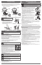
DECORATIVE TRIMMING
Decorative trimming is accomplished by removing all vegetation around trees, posts, fences, etc..
Rotate the whole unit so that the cutting head is at a 30° angle to the ground (Fig. 25).
F
ig. 23
Fig. 25
F
ig. 24
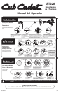
USING THE CUTTING BLADE
Before operating the unit with the cutting blade, stand in the operating position (Fig. 26). Refer to
Holding the Trimmer.
Cutting Blade Operating Tips
To establish a rhythmic cutting procedure:
• Plant feet firmly, comfortably apart.
• Bring the engine to full throttle before entering the
material to be cut. At full throttle the blade has maximum
cutting power and is less likely to bind, stall or cause
blade thrust (which can result in serious personal injury
to the operator or others).
• Cut while swinging the upper part of your body from left
to right.
• Always release the throttle trigger and allow the engine to
return to idle speed when not cutting.
• When you are finished, always unsnap the unit from the
harness before taking off the harness.
• Swing the unit in the opposite direction as the blade spins, which increases the cutting action.
• After the return swing, move forward to the next area to be cut and plant your feet again.
• The cutting blade is designed with a second cutting edge. You can use it by removing the blade,
turning it upside down and reinstalling it.
To reduce the chance of material wrapping around the blade, follow these steps:
• Cut at full throttle.
• Swing the unit into material to be cut from your left to
your right (Fig. 27).
• Avoid the material just cut as you make the return swing.
WARNING: Always wear eye, hearing, foot, body protection and the shoulder strap to reduce
the risk of injury when operating this unit.
WARNING: Do not use the cutting blade for edging or as an edger. Severe personal injury
to yourself or others can result.
WARNING: Blade thrust may occur when the spinning blade contacts an object that it
does not immediately cut. Blade thrust can be violent enough to cause the unit and/or operator to
be propelled in any direction, and possibly lose control of the unit. Blade thrust can occur without
warning if the blade snags, stalls or binds. This is more likely to occur in areas where it is difficult
to see the material being cut.
WARNING:
The blade continues to spin after the engine is turned off. The coasting blade
can seriously cut you if accidentally touched.
WARNING: Do not clear away any cut material
with the engine running or blade turning. To avoid
serious personal injury, turn off the engine. Allow
the blade to stop before removing materials
wrapped around the blade shaft.
Fig. 26
Fig. 27
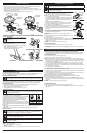
REPLACING THE SPARK PLUG
Use replacement #753-06193, a Champion® RDJ8J spark plug, or equivalent. The correct air gap is 0.025
inch (0.635 mm).
1. Stop the engine and allow it to cool. Grasp the plug wire firmly and pull it from the spark plug.
2.
Clean around the spark plug. Remove the spark plug from the cylinder head
by turning a 5/8-inch socket counterclockwise.
3. Replace a cracked, fouled or dirty spark plug. Set the air gap at 0.025 in.
(0.635 mm) using a feeler gauge (Fig. 34).
4. Install a correctly-gapped spark plug in the cylinder head. Tighten by
turning the 5/8-inch socket clockwise until snug.
If using a torque wrench torque to: 110-120 in.•lb. (12.3-13.5 N•m)
Do not over tighten.
LINE INSTALLATION
Always use original equipment manufacturer 0.095 in. (2.41 mm) replacement line.
1.
Align the arrows on the bump knob with the spool cover eyelets, if they are not already (Fig. 30).
2
. Using 16 ft. (4.8 m) of 0.095 in. (2.41 mm)
replacement line push both ends of the line
t
hrough the holes in the bump knob until they
p
rotrude through the eyelets on both sides of the
cutting head. Continue pulling the line until
a
pproximately 8 ft. (2.4 m) is visible from both
s
ides of the cutting head. (Fig. 31)
3
. Hold the spool cover, turn the bump knob
c
lockwise to wind the line around the spool
until about 5 in. (12.7 cm) is protruding from
e
ach side of the cutting head. (Fig. 31)
4
. Start the unit and bump the cutting head on the ground until the desired cutting length is achieved. Excess line will
b
e trimmed off by the line blade.
N
OTE: If the cutting line ends are pulled into the cutting head or the line becomes twisted, refer to Removing the Line.
AIR FILTER MAINTENANCE
Cleaning the Air Filter
Failure to maintain your air filter properly can result in poor performance or can cause permanent
damage to your engine.
1. Open the air filter cover. Push the locking tab on the top of the cover
inward, then pull the air filter cover out and down. (Fig. 32).
2. Remove the air filter (Fig. 32).
3. Wash the filter in detergent and water. Rinse the filter thoroughly and
allow it to dry.
4. Apply enough clean SAE 30 motor oil to lightly coat the filter.
5. Squeeze the filter to spread and remove excess oil.
6. Replace the filter.
NOTE: If the unit is operated without the air filter, you will VOID the warranty.
7. Reinstall the air filter cover. Position the slots on the bottom of the air filter cover onto the tabs at the
bottom of the back plate (Figs. 32).
8. Swing the cover up until the tab on the air filter backplate snaps into place in the slot on the air filter
cover (Fig. 32).
IDLE SPEED ADJUSTMENT
The idle speed of the engine is adjustable. An idle adjustment screw is between the air filter cover and
the engine starter housing (Fig. 33).
NOTE: Careless adjustments can seriously damage the unit. An authorized service dealer should make
carburetor adjustments.
If, after checking the fuel mixture and cleaning the air filter, the engine still will not idle, adjust the idle speed
screw as follows:
1. Start the engine and run for one minute to warm up. Refer to
Starting/Stopping Instructions.
2. Release the throttle trigger and let the engine idle. If the engine stops,
insert a small phillips screwdriver into the idle adjustment screw (Fig. 33).
Turn the idle speed screw clockwise 1/8 of a turn at a time (as needed)
until the engine idles smoothly.
3. If the engine appears to be idling too fast, turn the idle speed screw
counterclockwise 1/8 of a turn at a time (as needed), to reduce idle
speed.
Checking the fuel mixture, cleaning the air filter and adjusting the idle speed should solve most engine
problems. If not and all of the following are true:
• the engine will not idle
• the engine hesitates or stalls on acceleration
• there is a loss of engine power
Have the carburetor adjusted by an authorized service dealer.
Tab Lock
Fig. 32
WARNING:
The cutting attachment will spin during idle speed adjustments. Wear
protective clothing and observe all safety instructions to prevent serious personal injury.
WARNING: Do not sand blast, scrape or clean electrodes.
Grit in the engine could damage the cylinder.
Fig. 34
0.025 in.
(0.635 mm.)
Fig. 33
Idle Adjustment Screw
WARNING: To avoid serious personal injury, always turn the unit off and allow it to cool
before you clean or service it.
Arrows
E
yelet
T
ri
m
m
e
r L
i
n
e
F
ig
.
3
1
F
ig. 30
Air
Filter
Air Filter
Cover
T
ab