


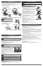
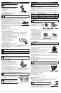
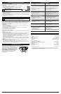
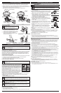
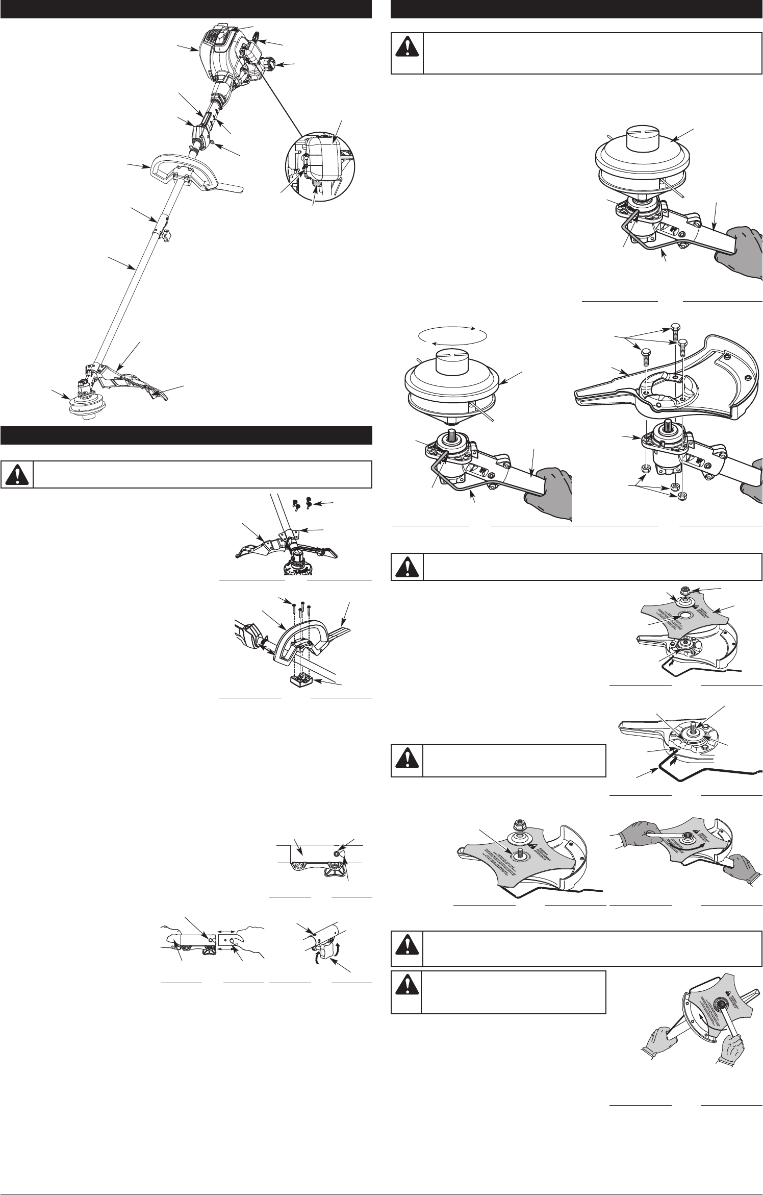
REMOVING THE BRUSH CUTTER BLADE
1. Align the shaft bushing hole with the locking rod slot and
insert the locking rod into the bushing hole (Fig. 11).
2. Hold the locking rod in place by grasping it next to the
shaft housing (Fig. 14).
3. While holding the locking rod, loosen the nut on the
blade by turning it clockwise with a 1/2 inch closed-end
or socket wrench (Fig. 14).
4. Remove the nut, blade retainer and blade. Store the nut
and blade together for future use in a secure place.
Store out of children’s reach.
REMOVING THE BRUSH BLADE GUARD
1. Loosen and remove the three guard bolts and nuts using a 7/16 inch closed-end or socket wrench
(Fig. 9). Store with brush cutter blade for future use.
WARNING:
To avoid serious personal injury,
always wear gloves while handling or installing
the blade.
WARNING: Do not sharpen the cutting blade. Sharpening the blade can cause the blade
tip to break off while in use. This can result in severe personal injury. Replace the blade.
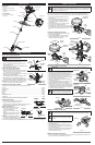
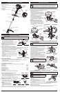
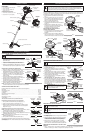
INSTALL THE CUTTING HEAD SHIELD
1. Place the cutting head shield onto the guard mount
bracket, making sure to align the holes on the shield with
the ones in the guard mount bracket. (Fig. 1)
2. Take the 4 shield screws and screw each one into the
shield until finger tight.
3. Using a Flat Head or T-20 screw driver, tighten the screws
until the shield is firmly in place.
INSTALL AND ADJUST THE D-HANDLE
1. Remove the screws and bottom clamp.
2. Place the D-handle over the shaft housing and onto the
bottom clamp (Fig. 1). Move it a minimum of 6 inches
(15.24 cm) from the end of the shaft grip.
3. Start the screws with an appropriate tool. Do not tighten
until making the handle adjustment.
4. If pre-installed, loosen the screws just enough to move it.
5. While holding the unit in the operating position (Fig. 23),
move the D-handle to the location that provides the best grip.
6. Tighten the clamp screws evenly until handle is secure.
NOTE: Make sure the barrier bar is on the operating side
when the unit is held in the operating position.
WARNING: To prevent serious personal injury, never operate the trimmer without the
cutting attachment shield in place.
3
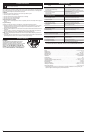
KNOW YOUR UNIT
APPLICATIONS
As a trimmer:
• Cutting grass and light weeds.
• Edging
•
Decorative trimming around trees,
fences, etc.
Throttle Control
D-Handle
S
haft Grip
M
uffler
Spark Plug
S
haft Housing
Starter Rope Grip
Line Cutting Blade
Choke Control
Lever
O
n/Off Control
Cutting Head
Cutting Head Shield
Fuel Cap
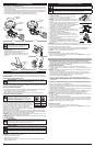
OPERATING THE RAPID-LINK™ SYSTEM
The Rapid-Link™ system enables the use of these optional Add-Ons.
Trimmer. . . . . . . . . . . . . . . . . . . . . . . . . . . . . . . . . . . . . . . . . . . . . . . . . . . . . . . . . . . . . . . . . . . . . . . AF720
Hedge Trimmer*. . . . . . . . . . . . . . . . . . . . . . . . . . . . . . . . . . . . . . . . . . . . . . . . . . . . . . . . . . . . . . . AH720*
Brushcutter* . . . . . . . . . . . . . . . . . . . . . . . . . . . . . . . . . . . . . . . . . . . . . . . . . . . . . . . . . . . . . . . . . . BC720*
Cultivator . . . . . . . . . . . . . . . . . . . . . . . . . . . . . . . . . . . . . . . . . . . . . . . . . . . . . . . . . . . . . . . . . . . . GC720
Edger*. . . . . . . . . . . . . . . . . . . . . . . . . . . . . . . . . . . . . . . . . . . . . . . . . . . . . . . . . . . . . . . . . . . . . . . LE720*
Pole Saw . . . . . . . . . . . . . . . . . . . . . . . . . . . . . . . . . . . . . . . . . . . . . . . . . . . . . . . . . . . . . . . . . . . . . PS720
Straight Shaft Trimmer . . . . . . . . . . . . . . . . . . . . . . . . . . . . . . . . . . . . . . . . . . . . . . . . . . . . . . . . . . SS725
Turbo Blower . . . . . . . . . . . . . . . . . . . . . . . . . . . . . . . . . . . . . . . . . . . . . . . . . . . . . . . . . . . . . . . . . . TB720
* Do NOT use this Add-On with an electric powered unit.
REMOVING THE ADD-ON
1. Turn the knob counterclockwise to loosen (Fig. 5).
2. Press and hold the release button (Fig. 3).
3. While firmly holding the upper shaft housing, pull the lower shaft
housing straight out of the Rapid-Link™ coupler (Fig. 4).
INSTALLING THE ADD-ON
NOTE: To make installing or removing the
add-on easier, place the unit on the
ground or on a work bench.
1. Turn knob counterclockwise to loosen
(Fig. 5).
2. While firmly holding the add-on, push it
straight into the Rapid-Link™ coupler
(Fig. 4).
NOTE: Aligning the release button with the
guide recess will help installation (Fig. 3).
3. Turn the knob clockwise to tighten (Fig. 5).
For decorative trimming/edging with the line cutting head, lock the release button into the 90° hole (Fig. 5).
ASSEMBLY INSTRUCTIONS
A
ir Filter Cover
Primer Bulb
Guide Recess
Fig. 3
Release
Button
Rapid-Link™
Coupler
Upper Shaft
Housing
Fig. 4
Lower Shaft
Housing
Primary Hole
Knob
Fig. 5
90˚ Edging Hole
(Trimmer Only)
R
apid-Link™
Throttle Lock-Out
Fig. 1
Guard Mount
Bracket
Screw (4)
Cutting
H
ead Shield
TOOLS REQUIRED:
• Flat head or T-20 screwdriver
• 3/8” socket
D-Handle
M
inimum 6 in.
(15.24 cm)
Fig. 2
Bottom
Clamp
Screw (4)
Barrier Bar
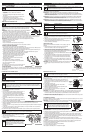
REMOVING THE CUTTING HEAD ATTACHMENT
If you want to trim or remove thicker, tougher and thornier brush you must use the metal brush cutter
attachment. This is supplied with its own blade guard which must be securely attached to the trimmer
head. In order to do this, both the cutting head attachment and cutting head shield must first be
removed from the trimmer unit. To safely attach the brush cutter to the unit follow these instructions:
1. Remove the cutting head shield from the shaft
housing (Fig. 1).
2. Position the cutting head attachment as shown
(Fig. 7). Align the shaft bushing hole with the
locking rod slot. Insert the locking rod into the
shaft bushing hole.
3. Hold the locking rod in place by grasping it next
to the boom of the shaft housing (Fig 7).
4. While holding the locking rod, remove the cutting
head attachment by unscrewing it clockwise (Fig.
8). Store the cutting head attachment for future
use.
INSTALLING THE BRUSH BLADE GUARD
1. Place the brush blade guard onto the trimmer head
with the three holes aligned.
2. Attach the blade guard to the trimmer head with
the three guard bolts and nuts using a 7/16 inch
closed-end or socket wrench (Fig. 9).
ASSEMBLY INSTRUCTIONS
Clockwise
Fig. 14
WARNING: Before using the brush cutter attachment make sure that only the metal
blade guard is attached to the trimmer head. Always make sure to remove the plastic cutting
guard shield when using the brush cutter attachment. Failure to do so may cause serious
personal injury or damage to the unit.
S
haft
Housing
S
haft
B
ushing
H
ole
Locking Rod
L
ocking
R
od Slot
Cutting Head
Attachment
Fig. 7
INSTALLING THE BRUSH CUTTER BLADE
1. Place the cutting blade on the output shaft bushing (Fig. 10).
2. Make sure that the cutting blade is centered on the pilot step
and sitting flat against the output shaft bushing (Fig. 12).
3. Align the shaft bushing hole with the locking rod slot and
insert the locking rod into the bushing hole (Fig. 11).
4. Put the blade retainer and nut on the output shaft. Make
sure that the blade is installed correctly.
5. Tighten nut counterclockwise against the blade while
holding the locking rod:
• If using a torque wrench and an 1/2 inch socket tighten
to: 325 - 335 in•lb, 27 - 28 ft.•lb, 37 - 38 N•m.
• Without a torque wrench, use a 1/2 inch closed-end or
socket wrench, turning the nut until the blade retainer is
snug against the shaft bushing. Make sure that the blade
is installed correctly, then rotate the nut an additional 1/4
to 1/2 turn counterclockwise (Fig. 13).
6. Remove the locking rod from the locking rod slot.
G
uard
Bolts (3)
Brush Blade
G
uard
Fig. 9
Nuts (3)
T
rimmer
H
ead
Shaft
Housing
C
utting Head
Attachment
U
nscrew
C
lockwise
S
haft
B
ushing
Hole
Locking Rod
L
ocking
R
od Slot
Fig. 8
WARNING: If the cutting blade is off-center, the unit will vibrate and the blade may fly
off, causing possible serious personal injury.
Pilot Step
Fig. 12
1/4-1/2 turn
Counterclockwise
Fig. 13
N
ut
B
lade Retainer
F
ig. 10
O
utput Shaft
Shaft
B
ushing Hole
Output
Shaft
B
ushing
Fig. 11
P
ilot Hole
Output Shaft
Bushing
C
utting
Blade
Locking Rod
L
ocking
Rod Slot
WARNING: To avoid serious personal injury or
damage to the unit, do not start or operate this
unit with the locking rod in the locking rod slot.