


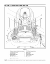
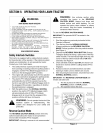
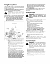

SECTION6: MAKINGADJUSTMENTS
,_ WARNING: Never attempt to make any
adjustments while the engine is running,
except where specified in the operator's
manual.
LevelingtheDeck
NOTE: Check the tractor's tire pressure before
performing any deck leveling adjustments. Refer to
Tires on page 25 for information regarding tire pressure.
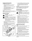
FrontTo Rear
The front of the cutting deck is supported by a stabilizer
bar that can adjusted to level the deck from front to rear.
The front of the deck should be between 1/4-inch and
3/8-inch lower than the rear of the deck. Adjust if
necessary as follows:
• With the tractor parked on a firm, level surface,
place the deck lift lever in the top notch (highest
position) and rotate the blade nearest the discharge
chute so that it is parallel with the tractor.
• Measure the distance from the front of the blade tip
to the ground and the rear of the blade tip to the
ground.
• The first measurement taken should be between
1/4" and 3/8" less than the second measurement.
• Determine the approximate distance necessary for
proper adjustment and proceed, if necessary, to the
next step.
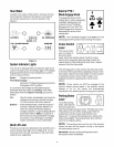
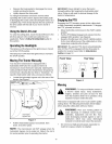
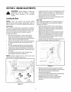
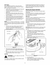
• Loosen the two jam nuts on the rear side of the
deck stabilizer bracket. See Figure 10
NOTE: Models equipped with a 42-inch deck have
only one jam nut, washer and lock nut.
Loosen Tighten
to lowerdeck to raisedeck
Figure 10
• Locate the two lock nuts on the opposite side of the
stabilizer bracket. See Figure 10. Tighten the lock
nuts to raise the front of the deck; loosen the lock
nuts to lower the front of the deck.
• Retighten the two jam nuts loosened earlier when
proper adjustment is achieved.
Sideto Side
If the cutting deck appears to be mowing unevenly, a
side to side adjustment can be performed. Adjust if
necessary as follows:
• With the tractor parked on a firm, level surface,
place the deck lift lever in the top notch (highest
position) and rotate both blades so that they are
perpendicular with the tractor.
• Measure the distance from the outside of the left
blade tip to the ground and the distance from the
outside of the right blade tip to the ground. Both
measurements taken should be equal. If they're
not, proceed to the next step.
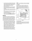
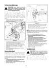
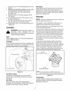
• Loosen, but do NOT remove, the hex cap screw on
the left deck hanger bracket. See Figure 11.
AdiustmentGear
HexB01t
Figure 11
• Balance the deck by using a wrench to turn the
adjustment gear (found immediately behind the hex
cap screw just loosened) clockwise/up or
counterclockwise/down.
• The deck is properly balanced when both blade tip
measurements taken earlier are equal.
• Retighten the hex cap screw on the left deck
hanger bracket when proper adjustment is
achieved.
17