


769-07498 P01 03/12
IMPORTANT: READ THE OPERATOR’S MANUAL THOROUGHLY AND FOLLOW THE SAFE OPERATION PRACTICES WHILE OPERATING THE UNIT.
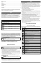
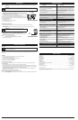
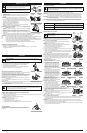
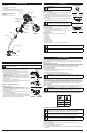
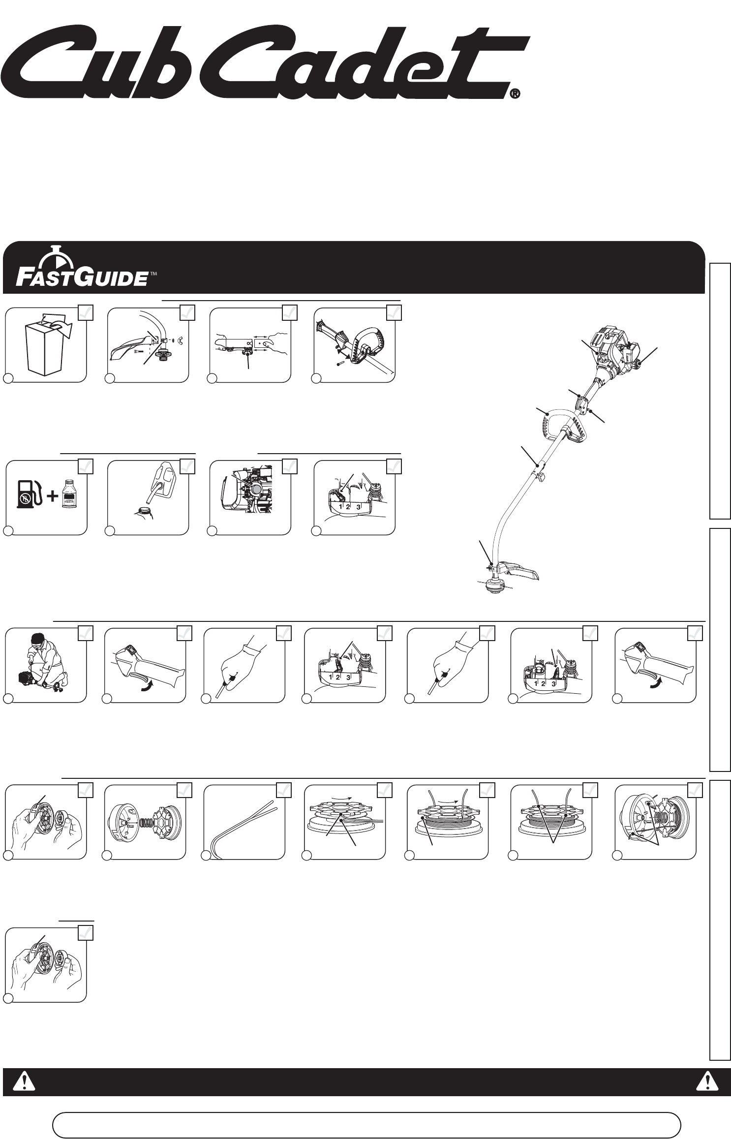
Removing Unit From Carton
Assemble The Unit
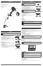
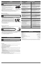
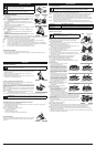
Starting The Unit
Slide shield’s slot onto
mounting bracket. Rotate
shield onto shaft. Push
square bolt through shield
and bracket. Tighten
washer and wing nut
onto bolt.
Remove the protective cap
and gray spacer from the
upper and lower shafts.
Push the attachment into
the coupler. Turn the knob
clockwise to tighten.
Assemble The Unit
Mix thoroughly in a separate
fuel can:
– 3.2 fl. oz. of 2-cycle
engine oil
– 1 gallon of unleaded
gasoline
NOTE: Do not mix directly in
the unit fuel tank.
Place unit on a level surface.
Fill fuel tank.
Press primer bulb 10 times,
or until fuel is visible
Crouch in starting position. SQUEEZE and HOLD
throttle for ALL further
steps.
Pull rope 5 times. Move choke lever to
Position 2 and squeeze
throttle.
Pull rope 3-5 times to start
engine. Run unit for 30-60
seconds to warm up.
Continue to squeeze
throttle. Move choke lever
to Position 3.
11 2
Remove all contents from
carton.
5 6 7
19 10
3
Loosen the bolt. Move the
handle to the location that
provides the best grip. Move
the handle a minimum of 6
inches away from the shaft
grip. Tighten the bolt until the
handle is secure.
Move choke lever to
Position 1.
Continue to squeeze
throttle. Run unit for an
additional 60 seconds to
complete warm-up. Unit
may be used during this
time.
8
4
Starting The Unit
11
12
13
14
15
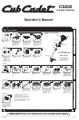
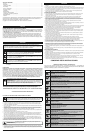
Primer
Bulb
10 X
5 X
3-5 X
Choke Lever
Starter Rope
Fuel Cap
Throttle Control
On/ Off Switch
D-Handle
Rapid-link™
Cutting Head Shield
Need Help?
Call 1-877-282-8684
Choke Lever
Choke Lever
Slot
Bracket
Min. 6”
ASSEMBLY TOOLS REQUIRED:
• 3/8” Socket
40:1
Knob
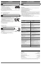
DIDN’T START?
Repeat the starting instructions.
If the unit still fails to start,
refer to the operator’s manual
for additional starting and
troubleshooting information.
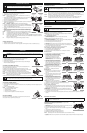
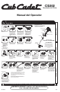
Bump
Knob
Inner
Reel
Outer
Spool
Spring
Top Hole
Bottom Hole
Split Wall
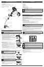
Unscrew the bump knob
counterclockwise.
Remove the inner reel and
spring.
Cut one 6-foot (1.8 m)
length of new 0.095” split
line trimming line. Split each
end about 6 inches (150
mm).
Insert the end of one line
into the top hole and the
end of the other line into the
bottom hole.
Wind the line tightly in the
direction shown on the inner
reel. The split wall will divide
the line. Wind the line until it
is completely divided and
about 6 inches (150 mm) of
line remains.
Insert the two 6-inch
sections into the two .095
holding slots.
11 2
Pass the two line ends
through the eyelets. Place
the spring inside the inner
reel. Insert the inner reel into
the outer spool. Push the
inner reel and outer spool
together.
Reloading The Line*
3
4
5
6
7
Hold the inner reel and outer
spool together. Firmly pull
the two line ends to release
them from the holding slots.
Screw the bump knob on
clockwise. Tighten the bump
knob securely.
18
Reloading The Line
Holding Slots
Eyelets
For replacement line, call 1-877-282-8684 or go to
an authorized service dealer.
For single line installation or replacement spool
installation instructions, refer to the Replacing the
Trimming Line section of this manual.
*This is to assist in the reloading of Splitline® only. These instructions
are NOT part of the fast assembly instructions. Line does not need to
be installed on the initial assembly and start-up.
Español — Page 11 English — Page 1Français — Page 6
NEED HELP? CALL 1-877-282-8684 IN U.S. OR 1-800-668-1238 IN CANADA
CS202
2-Cycle Trimmer
Operator’s Manual