


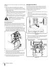
10. Slide the hex shaft through the right side of the frame
toward the left side and through the friction wheel
assembly.
NOTE: If the sprocket fell from the snow thrower chain
while removing the hex shaft, position the hex hub of the
sprocket toward the friction wheel and place the sprocket
in the chain.
11. After making certain that the chain is on both the large
and the small sprocket, align the hex shaft with the hex
hub of the small sprocket, and slide the shaft through
the sprocket.
12. Slide the spacer onto the end of the hex shaft.
13. Align the bearing on the right end of the hex shaft with
the hole in the right side of the frame, then push the
hex shaft to the left into position in the frame.
14. Slide the bearing onto the left end of the hex shaft and
press into the hole on the left side the frame.
15. Place the belleville washer (rounded side toward head)
onto the hex screw removed earlier, and insert the
screw into the threaded hole of the hex shaft.
16. Using a 3/4” wrench holding the hex shaft, gradually
tighten the hex screw to fully seat the bearings in each
side of the frame and to secure the hex shaft.
17. Position the frame cover on the bottom of the frame
and secure with the self-tapping screws, and re-install
the right wheel. Pivot the snow thrower down to its
normal operating position.
IMPORTANT: Repeat the drive control test from the
Assembly & Set-Up section of this manual before operating
the snow thrower.
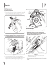
5. Holding the friction wheel assembly, slide the hex shaft
out of the right side of the frame. The spacer on the left
side of the hex shaft will fall and the sprocket should
remain hanging lose in the chain.
6. Lift the friction wheel assembly out between the axle
shaft and the drive shaft assemblies.
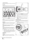
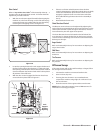
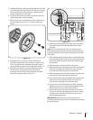
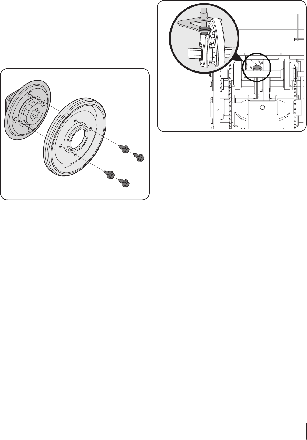
7. Remove four screws securing the friction wheel to the
hub assembly (refer to Fig. 7-11). Discard old friction
wheel.
8. Reassemble the new friction wheel onto the hub
assembly, tightening the four screws in rotation to 6-9
ft.-lbs. It is important to assemble the friction wheel
symmetrically for proper functioning. Refer to Fig. 7-11.
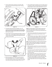
9. Reposition the friction wheel assembly in the snow
thrower frame. Insert the pin from the shift arm
assembly into the friction wheel assembly and hold
assembly in position. Refer to Fig. 7-12.
Figure 7-11
Figure 7-12
21Section 7 — Service