


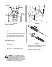
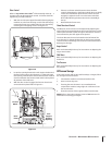
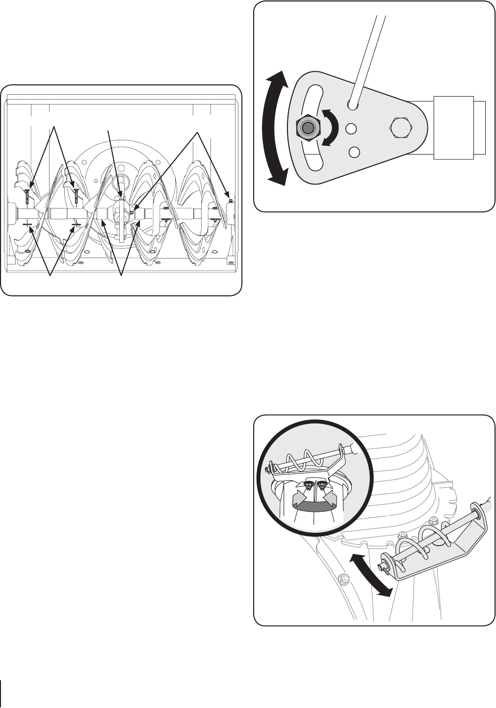
1. Place the shift lever in the fastest forward speed position.
2. Loosen the hex nut on the shift cable index bracket. See
Fig. 6-4.
3. Pivot the bracket downward to take up slack in the cable.
4. Retighten the hex nut.
NOTE: There are extra holes in the speed slector bracket
shown in Fig. 6-4 for further adjustment of the cable if
required.
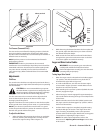
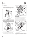
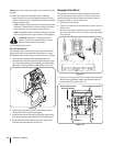
Chute Bracket Adjustment
If the spiral at the bottom of the chute directional control is not
fully engaging with the chute assembly, the chute bracket can be
adjusted. To do so:
1. Loosen the two nuts which secure the chute bracket and
reposition it slightly. See Figure 6-5.
2. Retighten the nuts.
Figure 6-5
Chute Directional Control
Once a season, lubricate the eye-bolt bushing and the spiral with
3-in-1 oil.
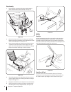
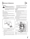
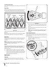
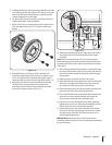
Auger Shaft
At least once a season, one at a time, remove the shear pins from
the auger shaft. Spray lubricant inside the hub of each auger
spiral assembly and around the spacers on the auger shaft. See
Figure 6-3.
Grease fittings can also be found at each end of the auger shaft.
Lubricate with a grease gun once a season. See Figure 6-3.
Gear Case
The auger gear case is equipped with a grease fitting. Lubricate
with grease once a season (order part number 737-0168). See
Figure 6-3.
NOTE: To relieve pressure, remove the vent plug before
lubricating the gear case. See Figure 6-3. Failure to do so could
result in damage to the gear case seals.
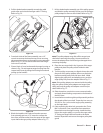
Augers
Each of the auger spiral assemblies is secured to the spiral shaft
with a shear pin and cotter pin. If the auger should strike a
foreign object or ice jam, the snow thrower is designed so that
the pins may shear.
1. If augers do not turn, check to see if pins have sheared.
2. Replace the pins if needed. Two replacement shear pins
and cotter pins have been provided with the snow thrower.
Spray an oil lubricant into shaft before inserting new pins
and securing with new cotter pins.
Adjustments
Shift Cable
If the full range of speeds (forward and reverse) cannot be
achieved, refer to the Figure 6-4 and adjust the shift cable as
follows:
Figure 6-4
Figure 6-3
Grease Fitting
SpacersBow-Tie Pins
Vent Plug
Shear Pins
16 Section 6— Maintenance & adjuStMentS