


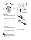
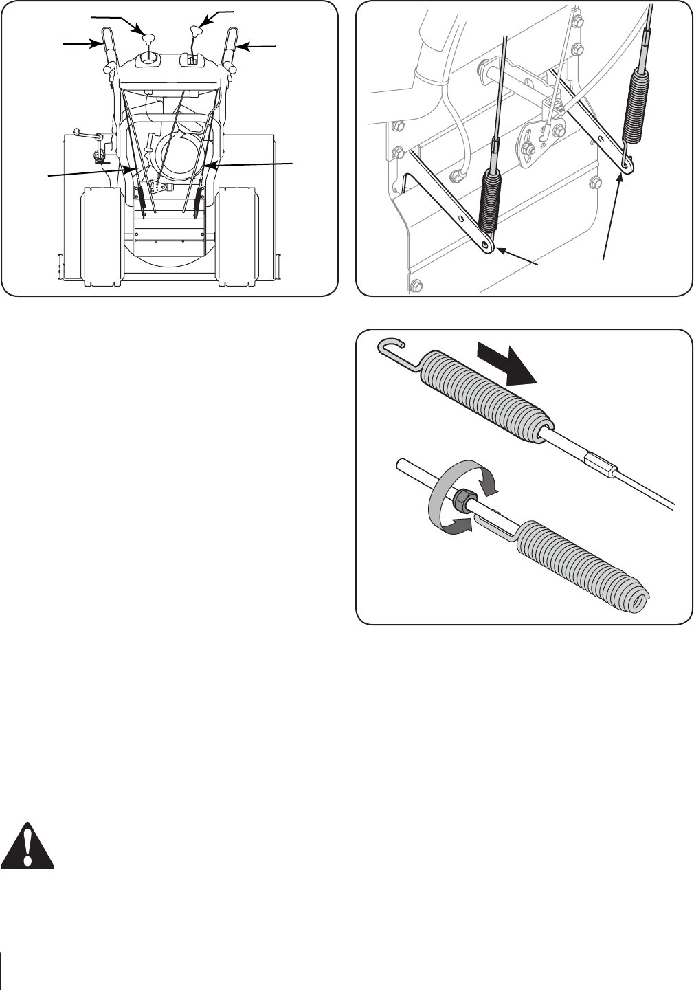
5. Securely hook each cable’s spring into the rear-ward most
hole of the respective actuator bracket. Both cables hook
into the rear-ward most hole of its bracket.
6. Repeat the wheel drive and auger control tests to verify
proper adjustment. Repeat previous steps if necessary to
attain proper adjustment of each cable.
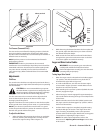
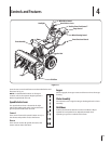
Testing Drive Control & Shift Lever
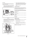
1. With the engine turned off, move the speed selector lever
into sixth (6) position. Refer to Figure 3-9.
2. With the wheel drive control released, push the snow
thrower forward, then pull it back. The machine should
move freely.
3. Engage the drive control and attempt to move the machine
both forward and back, resistance should be felt.
4. Move the shift lever into the fast reverse (R2) position and
repeat the previous two steps.
5. If you experienced resistance rolling the unit, either
when repositioning the shift lever from 6 to R2 or when
attempting to move the machine with the drive control
released, adjust the drive control immediately. See
Adjusting Drive and Auger Controls.
Adjusting Drive and Auger Controls
1. From beneath the handle, pull downward on the
appropriate cable and unhook the spring found on the end
of the cable from its respective actuator bracket. Refer to
Figures 3-9 and 3-10.
2. Slide the spring up the cable to expose the cable coupler
threads and lock nut. Refer to Figure 3-11.
3. Adjust the lock nut as follows: If adjusting the drive
cable, thread the lock nut outward (down the coupler) to
lengthen the cable and allow the unit to move freely when
the control is released. Thread the lock nut inward (up
the coupler) to shorten the cable to reduce slippage and
prevent the machine from being easily moved with the
drive control engaged.
WARNING! Do not over-tighten the cable. Over-
tightening may prevent the auger from disengaging
and compromise the safety of the snow thrower.
4. If adjusting the auger cable, thread the lock nut outwards
towards end of thread to lengthen the cable as necessary
to stop the auger from turning when the control is
released.
Figure 3-11
Figure 3-9
Figure 3-10
Drive
Control
Drive
Control
Cable
Auger
Control
Auger
Control
Cable
Speed Selector Lever
Chute Tilt Control
Rearward most hole of
the actuator brackets
10 Section 3— ASSembly & Set-Up