


7
over....use caution in (or avoid) areas where
the ROPS could come in contact with any
structures, trees, etc.
8. The ROPS and seat belt add additional mass
that elevates the machine’s Center of Gravity
(C.G.) which negatively affects the machine’s
stability and traction....use extra caution when
operating on slopes.
9. Inspect the ROPS and seat belt assemblies
on a regular basis for damage and improper
operation....replace all components that are
damaged or are not functioning properly with
authorized replacement parts.
10. Failure to use the seatbelt properly could
result in serious injury or death if an acciden
-
tal overturn occurs. In order for the ROPS to
be effective, the seat belt must be securely
fastened around the operator at all times
when the operator is on the machine. Contact
with the ROPS during an overturn could
cause serious injury or death.
11. The ROPS will not prevent the machine from
upsets or roll overs.
12. Only approved attachments should be used
on this machine.
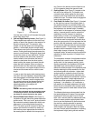
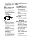
G. Suspension Seat
1. This unit is equipped with an adjustable sus-
pension seat system, which includes a fold-
forward seat with retractable seat belt
assembly, a low profile mechanical suspen
-
sion, and an Operator Presence Sensor
(OPS).
2. The seat bottom is covered with a heavy-
duty vinyl fabric and integrates the EVC
cushion comfort system that provides up to 1
3/8” dampered (for shock isolation) suspen
-
sion travel. An OPS in the form of a switch, is
integrated into the seat bottom and is con
-
nected to the machine electrical system. The
seat back is also covered with a heavy-duty
vinyl fabric, it adjusts to recline up to 16
degrees, and it will fold forward for transport
or protection from the elements of weather
(lever actuated on operator’s left side). The
armrests are adjustable for operator comfort
(knob inside armrests actuated from the bot
-
tom). Roller bearing single-locking tracks
provide easy repositioning fore/aft up to 5”
(lever actuated on lower right).
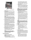
3. A mechanical suspension mechanism incor-
porates weight/ride adjustment controls for
operators in the 125 to 275 lb. weight range
(turn the knob on the front of the seat clock
-
wise to increase the weight capacity and
counter-clockwise to decrease. Self-lubricat
-
ing bearings are utilized throughout the sus-
pension mechanism that provides an
additional 2” of suspension travel.
4. A retractable seat belt assembly with inertia-
lock is attached to the “ride” portion of the
seat frame. The seat frame is attached to the
mechanical suspension, which is attached to
the roller tracks that are bolted to the seat
base in one of the three (3) locations - the
seat assembly can be detached and re-
installed 1” forward or 1” aft from the factory
installed position. When the two (2) hairpin
clips are removed from the frame-mounted
stud-bolts, the complete seat assembly and
seat base can be pivoted forward onto the
foot platform - this provides access to the
battery, hydraulic reservoir and filter, as well
as some of the electrical system and control
linkages. The seat base must be secured
with the hairpin clips prior to machine opera
-
tion.
Note: The seat base must be secured by
properly installing the hairpin clips into both
frame-mounted stud-botls, otherwise, the seat
assembly could tilt forward. The Operator
Presence Sensor must be connected to the
electrical wiring harness.