


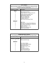

22
mower is parked with the engine shut off, the hydraulic
system locks the traction wheels.
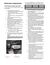
Note: To move the mower forward or in reverse
by pushing, you must release the dynamic braking.
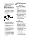
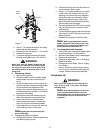
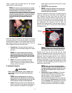
Locate the valves on the pump. Turn valves
counter-clockwise (using a standard 7/16” wrench)
one quarter turn to push the unit. After pushing the
mower to the desired location, return both valves
to the operating position by turning the valve
clockwise, but do not overtighten (See photo
below)
Left Side Pump
Bypass
Valve
.
When the mower is parked with the engine running and
the steering levers in the neutral position, the parking
brakes should be applied. The parking brakes are drum-
type brakes mounted on each traction wheel. They are
both engaged by the same operating lever.
1.
Adjustments:
The parking brake handle is an
overcenter lever that should engage with moder
-
ate force.
Note: To increase parking brake capacity,
adjust brake cables at the brake arms equally.
Adjust the cable housing nuts one full turn and
check parking capacity. Repeat if parking brake
does not hold.
2.
Repair:
The mower is equipped with drum
brakes and will not normally require mainte
-
nance. If they are not working properly, please
contact your service center.
F. Hydraulic System
WARNING:
Never overfill the hydraulic units. Damage can
occur if the oil level is not within the proper oper
-
ating range.
Note: When adding hydraulic oil, do so in
small quantities and recheck the oil level before
adding more. It is important that you do not over
-
fill the reservoir to allow for fluid expansion.
1.
Hoses:
Check the hoses from the hydraulic oil
tank to the oil filter to the hydraulic lines daily for
leaks or abrasion and replace any damaged
hoses. Make certain there are no kinks or twists
in any hose.
2.
Hydraulic Oil Tank and Filter:
Note: Change the hydraulic oil and the oil fil-
ter element after the first 50 hours of operation
and every 500 hours thereafter.
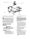
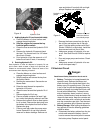
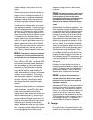
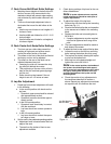
To drain the hydraulic oil tank, place a 2 gallon drain pan
under the drain plug on the bottom of the hydraulic oil
tank. Remove the drain plug, drain the tank, then
replace the plug. Remove the three screws from the top
of the oil filter and take out the oil filter element. You
don’t have to drain the rest of the hydraulic system. Put
the replacement filter element in the oil filter and
lubricate the sealing surface. Install the three screws in
the top of the oil filter to secure the oil filter element.
(See photo below)
Note: Always wipe off the hydraulic tank fill
cap and the area around it before removing the
cap to prevent dirt from contaminating the oil.
Remove the fill cap and fill the tank with the same
15W40 oil selected for the filter until the oil level is a 1/4”
below the oil tank fill neck. Leave this air space for
expansion. Start the engine and let it run at idle for
about five minutes. Check the filter for leaks. Idling the
engine and the pumps in this way will purge any air from
the system. Shut off the engine and recheck the oil level
in the tank. Top-off if necessary until the oil level is a 1/4”
below the oil tank fill neck.
Note: After unit is up to operating tempera-
ture, turn off engine and re-check hydraulic oil. If
oil appears foamy or contains excessive air bub
-
bles, DO NOT OPERATE UNIT. Contact service
technician.
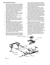
3.
Hydrostatic Pumps and Motors:
The pumps
are the hardest-working components in the
hydraulic system. They are in operation all the
time the engine is running. Because of
extremely close tolerances, wear is an important
factor in their life.
Contaminants
in the hydraulic
oil and
cavitation
does the greatest harm to the
pumps. Cavitation is a blockage in the supply
lines that produces a partial vacuum causing
Screw
Screw