


12
from
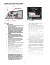
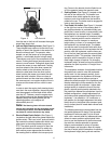
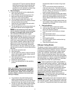
Steering Levers
Foot Pedal Lift
Figure. 3
the rear to the front will increase the engine
speed from slow to fast.
3.
Left and Right Steering Levers:
(See Figure 3.)
These hinged levers open out to the side in any
position to permit the operator to be seated or to
leave the mower’s seat. The operator, when
seated, can pull the levers up to the operating
position, a comfortable forearm’s length away.
These levers control all of the movements of the
mower. Pushing both levers forward causes the
mower to move forward. Pulling both levers back
causes the mower to move backward. Pushing
one lever ahead of the other lever causes the
traction wheel on the side where the lever is
ahead to rotate faster than the other traction
wheel, making the mower turn toward the side
where the lever is behind. When one lever is
pushed forward and the other lever pulled back
the same amount, one traction wheel will turn in
reverse and the mower will turn within its own
length.
In order to start the engine, both steering levers
must be in the neutral position; the parking brake
must be engaged; and the blade clutch switch
must be “off”. However, once the engine starts,
the parking brake must be released before the
operator places the steering levers into the
operating position or the engine will
automatically shut off.
Note: The Steering Lever will return toward
neutral when released, but they should be placed
in neutral by the driver. If the Drive Handles are
not placed in neutral, the tractor may creep.
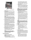
4. Electric Blade Clutch Switch:
(See Figure 1.)
Located on the right side of the mower beside the
ignition switch. This is an “on/off” push pull switch
that controls the electric blade clutch which sup
-
plies power to the cutting blades through the
PTO. The switch must be turned off to start the
engine and should be turned off for safety any
time another person approaches the mower or
the mowing deck is raised to the transport posi
-
tion. Power to the electric clutch will also be cut
off if the operator leaves the operator’s seat.
5.
Parking Brake:
(See Figure 2.) Located on the
left side of the traction unit. The handle is an
overcenter lever which applies the drum-type
brake on each drive wheel when the handle is
pulled to the rear. The brake must be engaged in
order to start the engine.
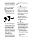
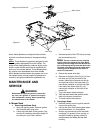
6.
Foot Pedal Lift Assist:
(See Figure 3.) Located
on the right front corner of the mowing deck. A
two pedal mechanism is provided whereby one
pedal (first) is used to raise, to momentarily hold
the implement at a desired height (if needed),
and to latch it in the transport or maximum height
setting. A second pedal is used to unlatch the
mechanism from the transport or maximum
height setting, to lower, or to momentarily hold
the implement at a desired height. The pedals
can also be used in conjunction with each other
when the upper portion of a foot activates the first
pedal to raise the implement, and the lower por
-
tion of the foot (heel) activates the second pedal
to release the latch. This provides a hands-free
operation with the exception of when an imple
-
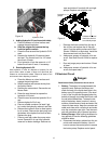
ment height change is required. For changing
implement height, at least one hand is required to
reposition the pins to provide 1/4” height-of-cut
increments.
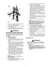
The mechanism includes: An adjustable location
foot pedal that is used to raise the implement
and/or latch it in the transport position, that is
directly connected to the implement lift linkage;
adjustable force counter-balance springs to
reduce the effective weight of the implement and
thereby reducing the forces needed on the first
and second pedals for activation - tighten both
springs equally to reduce the force at the foot
pedal; a second pedal pivotally attached to the
first pedal that releases the mechanism from the
latched configuration; a height adjustment link
and index provide predetermined height for the
implement - it is settable in 1/4” increments; a
lock position for the height adjustment link setta
-
ble by the pin in the highest (also transport posi-
tion) or lowest (also for mower deck removal and
installation).
The following features are incorporated into the
foot pedal implement lift design: Foot actuated
implement lift with one pedal (1st) for lift and
latch, with a second pedal for release and lower;
allows for some operators with physical limita
-
tions to use the implement lift mechanisms and
the machine; reduces potential for operator
fatigue; accommodates a variety of operator
sizes, shapes, and strengths; does not require
the use of hands (with the exception of resetting
the implement height) during normal machine