


23
violent bubbling in the hydraulic oil in the
pump.
Check the two suction hoses (the hoses con-
nected to the filter) daily before starting the
engine. Look for a flattened condition or any
leaks and repair or replace as necessary. A
flattened or leakng suction hose will permit
cavitation to develop which can destroy the
pumps in a short time.
Contaminants or foreign matter in the oil will
also damage the pumps . To prevent this, use
a filter that captures particles as small as 25
microns or 25 millionths of a meter in diame
-
ter. You can help in the battle against dirt by
being very careful when you remove or repair
a component in the hydraulic system. Thor
-
oughly clean off any component before you
work on it. Plug the ends of any hose or line
you remove with a rubber or plastic plug. Use
plastic caps to seal off the ends of hydraulic
fittings. Place any component you remove in a
clean plastic bag so it can’t pick up dust or
dirt. Clean your hands frequently when work
-
ing on the hydraulic components.
Note: The pumps are not owner-repairable.
If a pump fails, contact your Cub Cadet Com
-
mercial dealer. Do not disassemble the pump.
4.
Steering Lever Adjustments:
The steering
lever controls on this Zero Turn Mower (ZTM)
incorporate a patented interlock mechanism
that secures them in their Neutral position
whenever the Park Brake lever is applied.
Additionally, the lap bars can be opened in
any position - Neutral, when traveling For
-
ward, when traveling in Reverse, or when exe-
cuting a zero-turn maneuvar. The lap bars
also incorporate a Return-To-Neutral (RTN)
feature with hydraulic dampers to provide
smooth, non-jerkey, control motion while
affording an automatic hydrostatic braking
means.
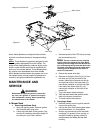
Whenever the Park Brake lever is moved rear-
ward to the Park Brake engaged position, a
cable mechanism, connected to each drum
brake on the hydrostatic wheel motors,
applies force to each brake lever so that each
wheel brake mechanism can prevent brake
drum and wheel rotation. At the same time, a
second cable and linkage mechanism is acti
-
vated to secure both lap bars in their Neutral
positions and to activate the Park Brake
switch. Both lap bars must be in their Neutral
positions for the neutral lock linkage to func
-
tion - the spring-loaded linkage will force rods
in through aligning holes in each lap bar
whenever the lap bars are in their Neutral
positions.
Note: Both lap bars must be in their Neutral
positions for the Park brake interlock mecha
-
nism to function so as to prevent lap bar
movement (movement that would activate the
hydrostatic pumps producing Forward or
Reverse travel rotation of the wheel motors)
and to allow the Park Brake switch to be acti
-
vated.
Whenever the Park Brake is applied (I.E., the
Park brake lever moved completely rearward
in the control panel slot), the lap bars should
be secured in their Neutral positions by the
linkage rods moving into the holes in the lap
bars. This lap bar Neutral lock mechanism
also activates the Park brake switch, which
allows for the engine to be started. If the lap
bars are in their Neutral positions, and they
are not “locked” so as to prevent movement
when the Park brake is applied, then the link
-
age from the RTN on the hydrostatic pumps
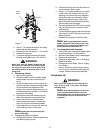
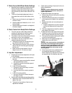
and the lap bars must be adjusted. This is
done by determining which side (or both) rod
is not aligned to the hole in the lap bar, then
locating that side linkage rod turn-buckle at
the hydrostatic pump RTN, loosening the jam
nuts and lengthening or shortening the link
-
age rod so that the rod snaps into the hole in
the lap bar.
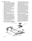
Dampers are incorporated into the lap bar
linkage to provide smooth, non-jerkey, control
action. The damper rate can be adjusted by
relocating the damper - lower to reduce the
damper action, and elevate to increase.
Note: The engine should be able to be
started whenever the Park Brake is applied,
and the lap bars are locked in their Neutral
positions - if not, the switch may need to be
adjusted or replaced.
5. Whenever the ZTM is on level ground with the
engine running and the lap bars in their Neu
-
tral positions, the ZTM should not creep (I.E.,
move in the Forward or Reverse directions of
travel). If this occurs, contact your Service
representative for the procedure to reset the
RTN mechanism on the hydrostatic pumps. If
the hydrostatic pump RTN is adjusted, the
control linkage must also be readjusted.
G. Storage
1.
General:
If your mower will not be in service
for a few months, it should be stored in a dry
location that is not subject to drastic changes