


21
• Slide the belt off of the variable-speed pulley
as you lift the pulley up and out through the
battery tray opening.
NOTE: Jacking the rear of the tractor up off the
ground and securing it with jackstands at this point in
the procedure will ease the following steps, but is not
necessary.
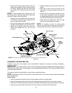
• Remove the rear idler pulley from the double-
idler bracket while unrouting the belt from
around both the rear and the front idler pulley.
Refer to Figure 16.
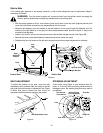
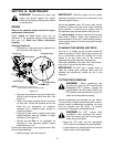
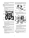
• Carefully unplug the tractor’s wire harness
from the connector on the electric PTO clutch.
See Figure 17.
Figure 17
• Remove the hex bolt from the center of the
electric PTO clutch and gently lower the
electric PTO clutch off of the engine
crankshaft. See Figure 17.
• The engine pulley is located directly above the
electric PTO clutch. Lower the engine pulley
far enough to be able to remove the upper
drive belt from around it.
IMPORTANT: When remounting the electric
PTO clutch, torque the center hex bolt to between 38
foot-pounds and 50 foot-pounds.
• Remove the drive belt by feeding it from both
ends toward the front idler pulley on the
double-idler bracket. See Figure 16.
• Reassemble by following the above steps in
reverse order.
• Reroute the new belt around the pulleys and
belt keepers EXACTLY as the old one was
routed. Refer to Figure 16.
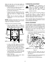
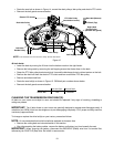
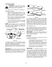
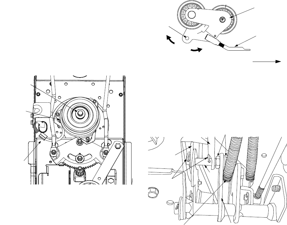
The drive pedal is properly adjusted when the hole
found in the double-idler bracket has approximately
1-3/8" of travel with ten pounds of pressure applied
to the drive pedal. See Figure 18.
Figure 18
Adjust the drive pedal after replacing the drive belts
on your tractor, if necessary, as follows:
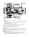
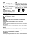
• Locate the speed control assembly on the
underside of the steering support bracket. See
Figure 19.
Figure 19
• Remove both hairpin clips from the pin which
is fastened to the speed control assembly (be
careful not to lose the small flat washers found
on the pin). See Figure 19.
• Remove the drive pedal return spring.
• Using two 9/16" wrenches, remove the pin
from the speed control assembly. See Figure
19.
Thread the idler adjustment rod inward or outward to
lengthen or shorten the travel of the double-idler
bracket until proper adjustment is achieved.
• Reassemble by following the above steps in
reverse order.
NOTE: View shown from beneath tractor.
Hex Bolt
Electric
PTO Clutch
Connector
Front of Tractor
NOTE: View shown from above tractor.
Double-idler
Bracket
Idler
Adj. Rod
Hole
1
-
3
/
8
"
Speed Control
Assembly
Hairpin
Clips
Idler
Adj. Rod
Pin
Drive Pedal
Return Spring
Place Wrenches Here
Neutral
Return
Bracket