


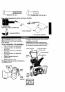
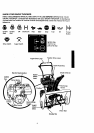

TO REMOVE SNOW THROWER
FROM CARTON
• Locate and remove container of 5W30 oil.
• Locate all parts packed separately and
remove from the carton.
NOTE: Place fuel stabilizer in a safe place
until needed for storage.
• Remove and discard the packing material
from around the snow thrower.
• Cut all four comers of the carton from top
to bottom and lay the panels flat.
• Roll the snow thrower off the carton by
pulling on the lower handle. CAUTION:
DO NOT back over cables.
• Remove the packing material from
handle assembly and plastic protector on
top of auger housing.
• Cut ties securing the clutch control cables
to the lower handle and lay cables back
away from the motor frame.
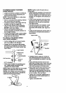
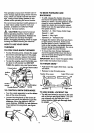
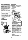
TO INSTALL THE UPPER HANDLE
AND CRANK ASSEMBLY
• Cut tie holding shift rod to lower handle
and move shifter to the first gear.
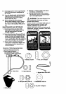
• Loosen, but do not remove the screws,
flatwashers, Iockweshers and hex nuts in
the upper holes of the lower handle. See
figure below.
Upper handle
Loosen do not
remove
11/32_ Ratwasher
5/16" hex Nut .-,
5/16 X 2"
5/16"
• Raise upper handle into operating posi-
tion. Upper handle should be to the
outside of the lower handle.
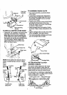
NOTE: Make sure the cables are not caught
between the upper and lower handle.
NOTE: If the cables have become discon-
nected from the clutch levers, reinstall the
cables as shown in figure below.
"Z' fitting
NOTE: Position cable through slots on
shifter plate.
• Install hardware supplied in the parts bag
(Screw, flatwasher, Iockwasher, and hex
nut) into middle hole on right hand side of
handles. Do not tighten until all bolts are
in place.
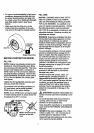
• Locate crank assembly removed earlier
and remove the 3/8" nylon Iocknut and
flatwasher from the eye bolt assembly.
See figure below.
• Reinstall flatwasher and adapter. Install
eye bolt through lower hole in the left
hand side of the handle. See figure be-
low.
• Install the 3/8" flatwasher and the 3/8" ny-
lon lock,nut on the eye bolt as shown in
figure below.
3/8" nylon
Iocknut
e Bolt
Ratwssher
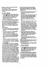
Carefully remove cotter pin, clevis pin
and universal joint pin from yoke end of
crank rod assembly as shown in next fig-
ure.
• Place universal joint into end of worm
gear lining up large holes. Insert universal
joint pin (ensure opening in pin is in line
with small openings in universal joint).
• Place yoke end of crank rod around uni-
versal joint, lining up openings. Insert
clevis pin through assembly and secure
with cotter pin. Spread ends of cotter pin
to lock in,place. See next figure.
• Tighten nut on eye bolt, keeping eye in
line with the rod while tightening the in-
side securely.
• Tighten all handle bolts.