


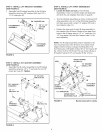
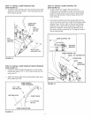
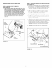

STEP7: iNSTALL TILT BRACKET ASSEMBLY
(SEE FIGURE 6 ON NEXT PAGE)
* Loosen the bolts end nuts on the tilt bracket
assembly 1/4 turn or until the two plates of the
assembly will slide back and forth. You will retighten
them later in step 25.
Lightly apply grease to the end of the arm on the tilt
anchor assembly and install the tilt bracket assembly
to the arm using a 1/2" x 1" hex bolt (C) and 1/2" hex
lock nut (N). Tighten then loosen the nut 1/4 turn, or
until the tilt bracket assembly pivots freely.
Install the 1/4" x 2" hex bolt (I) through a 1/4" washer
(CC), the 1" long spacer (V) and then through the end
of the extension spring on the tilt bracket assembly.
Next, insert the end of the bolt into the hole in the arm
of the tilt anchor assembly and install the slotted stop
bracket (NN), a 1/4" washer (CC) and a 1/4" nylock
nut (T) onto the bolt. Tighten.
1/4" NYLOCK NUT (T)
1/4" WASHER
SLOTTED STOP
BRACKET (NN) \
TILT ANCHOR
ASSEMBLY
1/4" WASHER (CC)
1/2" x 1"
HEX BOLT (C)
r
1" SPACER (V) /
APPLY
1/4" x 2" / GREASE
HEX BOLT (I) 1/2" HEX
LOCK NUT (N)
TILT BRACKET
ASSEMBLY
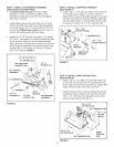
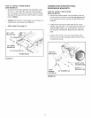
STEP 8: INSTALL DUMP PIVOT BRACKET
(SEE FIGURE 7)
* Install a 1/8" x 1-1/2" cotter pin (AA) to the inside hole
in the shaft shown in figure 7, and then install a 1"
washer (KK) onto the shaft. Apply grease to the end of
the shaft and install the dump pivot bracket assembly
onto the shaft. Install a 1" washer (KK) onto the shaft
and secure it using a 1/8" x 1-1/2" cotter pin (AA).
1/8" x 1-1/2"
COTTER PiN (AA)
\
/-_'_ 1" WASHERS (KK)
APPLY
GREASE
1/8" x 1-1/2"
COTTER PiN (AA)
DUMP PIVOT
BRACKET
FIGURE 7
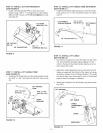
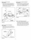
STEP 9: iNSTALL DUMP CONTROL ROD
(SEE FIGURE 8)
* Install a 1/8" x 1-1/4" cotter pin (Z) into the inside hole
in each end of the dump control rod. Spread the ends
of the cotter pins and wrap around the rod. Install a 5/8"
washer (HH) onto each end of the control rod.
Install the dump control rod to the dump pivot bracket
and bucket. Fasten using two 5/8" washers (HH) and
1/8" x 1-1/4" cotter pins (Z). Spread the ends of the
cotter pins and wrap around the rod.
FIGURE 6
1/8" x 1-1/4"
COTTER PiN (Z)
5/8" WASHERS (HH)
x 1-1/4"
COTTER
PiNS (Z)
1/8" x 1-1/4"
COTTER PiN (Z)
5/8" WASHERS (HH)
DUMP
CONTROL
ROD
FIGURE 8