


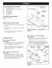
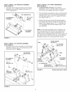
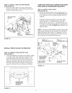
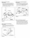

STEP 17: iNSTALL HOSE CLiP AND SPACER
(SEE FIGURE 16)
Secure the dump cable to the back of the bucket
using a hose clip (QQ), a #10 x 5/8" truss-head bolt
(L) and a #10-32 nylock nut (U).
#10-32 NYLOCK
NUT (U)
/
a..
#10 x 5/8"
'_....,
HOSE TRUSS
CLiP (QQ) HEAD BOLT (L)
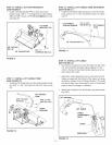
LAWN TRACTORS AND GARDEN TRACTORS
WiTH SINGLE SUSPENSION BRACKETS
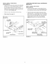
STEP 19: iNSTALL SiDE PLATES
(SEE FIGURE 18)
Remove any bolts present in the mounting holes on
the left side of the tractor frame. Do not remove bolts
from right side of frame until left side plate has been
installed.
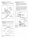
Install the left (long) side plate on the tractor frame
using three 3/8" x 1" carriage bolts (J), three 3/8"
nylock nuts (R), one 5/16" x 1" carriage bolt (K), one
5/16" nylock nut (S) and three large 1/2" washers (11)if
needed (see note). Do not tighten yet. Repeat for the
right side plate.
NOTE: If an engine mounting plate is present (shown with
dotted lines) that prevents the side plate from resting flat
against the tractor frame, place 1/2" washers (ll) on the
front two 3/8" bolts and on the rear 5/16" bolt to serve as
shims between the side plate and the frame.
FIGURE 16
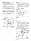
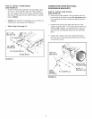
INSTALL FRONT SCOOP ON TRACTOR
STEP 18: iDENTiFY YOUR TRACTOR TYPE
(SEE FIGURE 17)
Look underneath the front axle of your tractor. If there
is a single mower deck suspension bracket located
under the middle of the front axle, continue on to
step 19. If your tractor does not have a mower deck
suspension bracket underneath the middle of the
front axle, skip to step 21 on page 13 or step 23 on
page 14 for tractors with dual suspension brackets.
(3) 3/8" x 1"
CARRmAGE BOLTS (J)
(SEE NOTE)
LEFT (LONG)
SiDE PLATE
5/16" × 1"
CARRIAGE BOLT (K)
ENGmNE
MOUNTmNG
PLATE
5/16"
NYLOCK
NUT (S)
(3)3/8" NYLOCK
NUTS(R)
FIGURE 18
MOWER DECK
SUSPENSION
BRACKET
FIGURE 17
12