


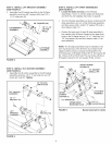
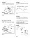
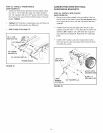

STEP 10: iNSTALL TiLT STOP BRACKETS
(SEE FIGURE 9)
Install a tilt stop bracket (PP) to each side of the
bucket using a 3/8" x 1" carriage bolt (J), 3/8" washer
(EE) and 3/8" nylock nut (R). Do riot tighter= the nuts
until step 27.
TILT STOP
BRACKET (PP)
318" NYLOCK
NUT (B) 3/8" x 1" J_
318"WASHER (EE) CARRIAGE BOLT (J)
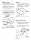
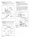
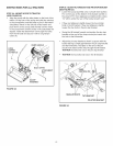
STEP 12: iNSTALL LiFT HANDLE TUBE EXTENSION
(SEE FIGURE 11)
Install the lift handle tube extension on the lift handle
tube using a 1/4" x 1-3/4" hex bolt (H) and 1/4" nylock
nut (T).
LIFT HANDLE 1/4" x 1-3/4"
TUBE EXTENSION HEX BOLT (H) LIFT HANDLE
_, TUBE
1/4" NYLOCK NUT (T)
FIGURE 11
FIGURE 9
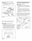
STEP 11: iNSTALL LiFT HANDLE TUBE
(SEE FIGURE 10)
Install the lift handle tube into the index bracket using
two 5/16" x 1-3/4" hex bolts (G) and 5/16" nylock nuts
(S).
LIFT HANDLE
TUBE
5/16" NYLOCK 5/16" × 1-3/4"
NUTS(S) _\k HEX BOLT (G)
/ INDEX
FIGURE 10
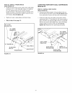
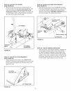
STEP 13: iNSTALL LiFT CABLE
(SEE FIGURE 12)
Connect the hooked end of the lift cable into the index
rod, and install the threaded cable adjuster into the
notch in the top of the index bracket, placing a nut on
each side of the notch.
Adjust the cable adjustment nuts so that when the lift
trigger is squeezed, the bottom of the index rod raises
enough to release from the latched position. The index
rod should also lower far enough to lock in the latched
position when the trigger is released.
Attach the lift cable to the lift handle using three cable
ties (OO).
LIFT TRIGGER
LIFT CABLE
CABLE
NUTS
INDEX ROD
FIGURE 12
10