


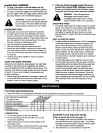

&
CAUTION: Before servicing or adjusting
the snow thrower, shut off the engine,
remove the spark plug wire(s), set the
parking brake and remove the key from
the tractor ignition.
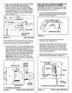
REPLACING AUGER DRIVE BELT
• Lower the snow thrower to the ground.
• Remove the attachment pin. See figure 22.
• Lock the snow thrower's lift handle in the down
position to decrease belt tensidn.
• Release the spring tension from the auger belt idler
arm on the bottom of the Clutch/idler assembly.
• Remove the auger drive belt from the clutch/idler
assembly and from the spiral auger housing.
• Install new belt over top of large auger drive pulley
and under the two side idler pulleys. Twist the belt
1/4 turn to seat the "V" of the belt in the groove of
each idler pulley.
Assemble the belt onto the clutch/idler assembly
per the instructions on page 13.
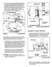
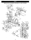
SKID SHOE ADJUSTMENT
• The skid shoes are mounted on each side of the
spiral auger housing. They regulate the distance
the scraper plate is raised above the plowing
surface. When removing snow from a gravel
driveway or and uneven surface, it is advisable to
keep the scraper plate as high above the surface
as possible to prevent possible damage to the
spiral auger. On blacktop or concrete surface, keep
the scraper plate as close to the surface as pos-
sible.
• Raise the snow thrower off the ground and place a
block under each end of the scraper plate. Loosen
the six hex nuts securing the skid shoes to the
housing. Adjust the skid shoes up or down to the
desired position and tighten the nuts securely.
Adjust both skid shoes to the same height to keep
the housing and the scraper plate level. See figure
28.
FIGURE 28 -
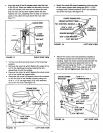
LIFT RELEASE CABLE ADJUSTMENT
• If the lift rod does not lock the snow thrower
. securely in the transport position, loosen the upper
hex nut on the lift bracket a few turns and tighten
the lower hex nut. See figure 17 on page 11.
• If the lift rod falls to unlock completely to lower the
snow thrower, loosen the lower hex nut on the lift
bracket a few turns and tighten the upper hex nut.
Refer to figure 17 on page 11.
DISENGAGEMENT ADJUSTMENT
(Only units wlth manual attachment clutches)
If the spiral auger on the snow thrower do not stop
when the attachment clutch lever on the tractor is in
the disengaged position, then adjustment is neces-
sary. Proceed as follows. Refer back to figure 10.
• Place the attachment clutch lever in the disen-
gaged position.
• Remove the hairpin cotter from the engagement
rod trunnion and lift the trunnion out of the hole in
the idler arm.
• Screw the trunnion a few turns towards the front
end of the rod.
• Replace the trunnion into the hole in the idler arm
and secure it with the hairpin cotter.
Check the operation of the snow thrower. If the
spiral augers still do not stop, repeat the above
steps until the augers stop when the attachment
clutch lever is placed in the disengaged position.
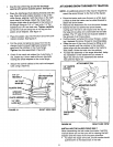
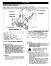
SPIRAL AUGERS
• The spiral augers are secured to the auger shaft
with two shear bolts and hex lock nuts. If you hit a
foreign object or if ice jams the augers, the snow
thrower is designed so that the bolts will shear.
• If the augers will not.turn, check to see if the shear
bblts have sheared. See figure 29. Two replace-
ment shear bolts and hex lock nuts have been
provided with the snow thrower. For future use
order part number 710-0890A shear bolt and
number 43064 hex lock nut.
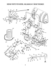
GEAR HOUSING
SKID SHEAR BOLT AND SCRAPER
SHOE HEXLOCKNUT PLATE
FIGURE 29
17