


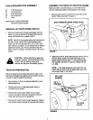
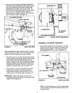
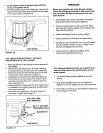

Attachthe snow thrower's clutch/idler assembly to
the tractor frame by sliding the notched arms at the
rear of the assembly onto the two shoulder bolts
assembled to the inside of the tractor frame. Lift
the front of the assembly so that the sides fit inside
the R.H. and L.H. hanger brackets. Attach the
assembly to the brackets using two pivot lock pins
and 1/8" hairpin cotters. See figure 14.
_ 1/8" HAIRPIN COTTER
P,VOTLOCKP,N
'\
FIGURE 14 RIGHT SIDE VIEW
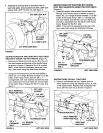
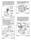
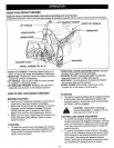
When assembling the belt under the tractor, hold this
manual above you so that you will be viewing the belt
diagram and the tractor from the same direction.
Assemble the short "V" belt onto the engine pulley
_sothat it passes between the pulley and the engine
pulley keeper. Next assemble the belt onto the
large rear pulley on top of the clutch/idler assembly,
passing it between the pulley and the keeper bolt
located beside the pulley. Position the idler pulley
against the outside of the belt. See figure 15.
• Place tension on the belt, by pulling the left side
tensioning chain as far out as the assembled
• hairpin cotter will allow. Secure the chain in this
position with a 1/8" hairpin cotter. See figure 15.
IMPORTANT: Make sure that the "V" belt is not
assembled around the outside of the engine pulley
keeper or the keeper bolt.
ENGINE
IDLER PULLEY PULLEY
,:_ KEEPER
0
KEEPERBOLT\
1/8" HAIRPIN
_.L C01-FER
LEFT SIDE OF TRACTOR
FIGURE 15
VIEWED FROM UNDERNEATH
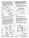
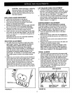
ASSEMBLY OF SNOW THROWER
r_
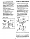
• Place the lift handle into the lift bracket on the right
side of the snow thrower. Fasten the handle to the
bracket using two 5/16" x 1-3/4" hex bolts, 5/16"
lock washers and 5/16" hex nuts. See figure 16.
LIFT HANDLE
\
5/16" HEX NUT / \ 5/16" x 1-3/4"
/
\
HEX BOLT
6116" LOCK
WASHER
LIFT BRACKET
FIGURE 16 RIGHT SIDE VIEW
HINT: For easier assembly of the lift release cable
in the next step, tilt the snow thrower forward onto
the spiral auger.
10