


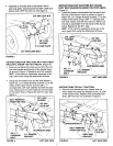
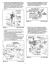
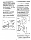

Coat the top of the ring around the discharge
opening with general purpose grease. See figure 21.
Place the discharge chute (facing forward) onto the
ring. Place the anti-rotation bracket on top of the
chute flange, aligning it with the holes on the right
hand side of the flange. Attach the three chute
keepers (right side up as shown) to the bottom of
the flange using six 1/4" x 1" hex bolts, 1/4" flat
washers and 1/4" hex lock nuts. Tighten carefully
so that the nuts are snug but do not dig into the
plastic chute keepers. See figure 21.
Place the plastic cap onto the short end of the anti-
rotation bracket, See figure 21.
Pull the crank.rod spiral out away from the dis-
charge chute to prevent tightness between the
spiral and the notches in the chute flange.
Tighten the n_ts assembled in figure 20
Check if the crank rod rotates the chute freely. If
not, loosen by 1/4 turn each of the six hex bolts
holding the chute keepers to the chute flange.
Secure the control cables to the crank rod support
tube using a nylon tie.
1/4" x 1"
HEX BOLT
1/4" FLAT
PLASTIC CAP..._
• _l
GREASED
I /
ANTI-ROTATION
BRACKET
/
FLANGE
CHUTE KEEPER
1/4" HEX
LOCK NU_._
FIGURE 21
RIGHT SIDE VIEW
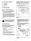
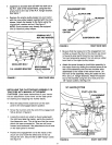
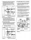
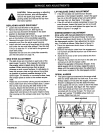
A'I-rACHING SNOW THROWER TO TRACTOR
NOTE: An additional person's help may be required to
mount the snow thrower to the front of the tractor.
• Place the tractor and snow thrower on a flat, level
surface so that the tractor can be rolled forward to
attach the snow blower.
• Remove the Attachment Pin from the snow thrower,
• Extend the belt out behind the snow thrower,
making sure the belt is still looped over the top of
the large drive pulley and underneath the two idler
pulleys. The "V" side of the belt must be seated in
the grooves of all three pulleys.
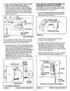
• Roll the tractor up behind the snow thrower, center-
ing it between the snow thrower's mounting plates.
• Raise the rear of the snow thrower by lifting up on
the lift handle until the notches in the mounting
plates align with the shoulder bolts in the tractor's
side plates. Guide the bolts into the notches.
• To ease the assembly of the auger drive belt, delay
the installation of the attachment pin shown in
figure 22 until you have assembled the belt as
instructed for figure 23.
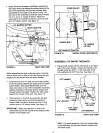
1/8" HAIRPIN
co'n'ER
\
A'I-rACHMENT PIN
SHOULDER
BOLT
FIGURE 22
RIGHT SIDE VIEW
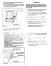
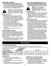
INSTALLING THE AUGER DRIVE BELT
When assembling the belt under the tractor, hold this
manual above you so that you will be viewing the belt
diagram and the tractor from the same direction.
• To attach the auger drive belt, the lift handle should
pushed down to increase slack in the belt.
12