


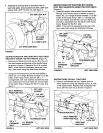
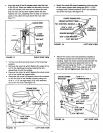

Insert the end of the lift release cable into the hole
in the lift rod. Place the cable into the slot in the top
of the lift bracket, with one hex nut above the slot
and one hex nut and lock washer below the slot.
Tighten the nuts, adjusting them to take out excess
stack in the cable wire just above the nuts. See
figure 17.
/ CABLE WIRE
__ _Jj.HEXNU
LOCK
- w!ill!
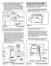
o. Attach the chute tiJtcontrol assembly to the top side
of the crank support tube using two 5/16" x 1-3/4"
carriage bolts, bowed washers, 5/16" lock washers
and 5/16" hex nuts. See figure 19.
CHUTE CRANK ROD "_'_'_""_X_
CRANK SUPPORT TUBE .-_,._.,_
TILT CONTROL HANDLE--_Q .7_
,, _, a_._ -WTILT
5/16 x1-3/4 ---.--"_'_'_J.___CC'I'NTROL
BOWEDWAST
5/16" LOCKWASHER _e
5/16" HEX NUT J"
FIGURE 19 LEFT SIDE VIEW
FIGURE 17
RIGHT SIDE VIEW
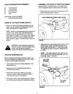
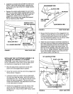
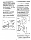
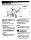
• Tilt the snow thrower back down to the horizontal
position.
• Remove the nylon tie which fastens the auger drive
belt to the discharge housing, leaving the belt
assembled around the pulleys.
• Remove the nylon tie which fastens the chute crank
rod to the crank rod support tube.
• Assemble the crank rod support tube to the bracket
on the left side of the thrower housing using two
5/16" x 1-1/4" carriage bolts, 5/16" lock washers
and 5/16" hex nuts. See figure 18.
CRANK ROD
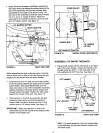
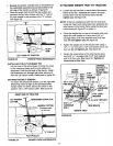
• Attach the chute crank rod assembly brackets to
the plastic bracket on the left side of the thrower
housing. Align the chute crank bracket beneath the
rod support bracket and assemble both to the
plastic bracket using two 5/16" x 1" carriage bolts,
5/16" flat washers, 5/16" lock washers and 5/16"
hex nuts. Do not Ughten yet. See figure 20.
CHUTECRANK "_16"x1"
BRACKET
CHUTE
CRANK
ROD
ROD />--7j
SUPPORT
BRACKET / /
5/16" F
WASHER
'16" LOCK _
WASHER
5/16" HEX NUT
FIGURE 20
LEFT SIDE VIEW
FIGURE 18
LEFT SIDE VIEW
11