


9
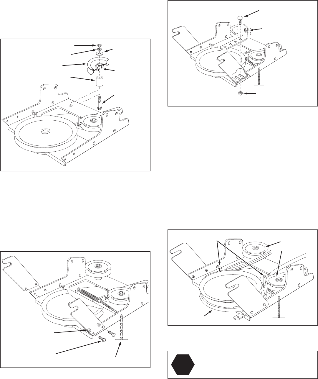
3/8" X 3-1/4"
HEX BOLT
(B)
LARGE SPACER (SS)
PULLEY (TT)
3/8" LOCKWASHER (S)
3/8" HEX LOCK NUT (DD)
3/8"
WASHER (X)
LONG END
OF HUB
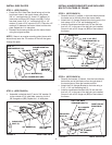
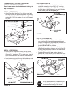
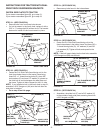
STEP 7: (SEE FIGURE 7)
• Attachthepulley(longendofhubfacingdown)and
the large spacer (SS) to the hole shown in the clutch/
idler assembly. Use a 3/8" x 3-1/4" hex bolt (B), a 3/8"
washer (X), a 3/8" lock washer (S) and a 3/8" hex lock
nut (DD).
FIGURE 7
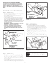
FIGURE 9
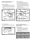
STEP 9: (SEE FIGURE 9)
• Attachthecablebrackettotheslotshowninthe
clutch/idler assembly using a 5/16" x 3/4" carriage
bolt (O) and a 5/16" nylock nut (CC). Place the bolt in
the front hole of the bracket and in the end of the slot
closest to the pulley. Do not tighten yet.
CABLE
BRACKET
5/16" x 3/4"
CARRIAGE BOLT (O)
5/16" NYLOCK
NUT (CC)
THIS SECTION IS FOR TRACTORS WITH A
MANUAL ATTACHMENT CLUTCH
If your tractor has an electric attachment clutch go to
step 14 on page 11.
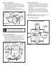
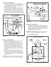
FIGURE 10
HEX BOLTS
(#48138)
DRIVE BELT
FLAT IDLER
PULLEYS
STOP
Didyouselectthecorrectdrivebeltforyour
tractor? Using the wrong length belt may
cause premature bearing or belt failure.
STEP 10: (SEE FIGURE 10)
• Twodifferentlengthdrivebeltsareincludedwith
your snow thrower. Tractors with manual attachment
clutches and single front deck suspension brackets use
the56"drivebeltwith#48138 printed on the outside of
the belt. DO NOT USE the other belt.
• Slightlyloosenthehexboltnexttotheatidlerpulley.
Installthedrivebeltdownbetweenthehexboltandthe
atidlerpulleywiththeatsideofthebeltagainstthe
pulley. Retighten the hex bolt.
• Loopthebeltaroundthelargev-pulley,placingit
betweenthev-pulleyandthehexboltnexttothepulley.
Placethebelttotheinsideoftheotheratidlerpulley.
5/16" NYLOCK
NUT (CC)
5/16" x 3/4"
HEX BOLT (E)
TENSIONING CHAIN (PP)
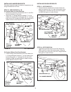
FIGURE 8
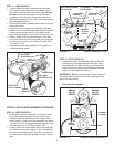
STEP 8: (SEE FIGURE 8)
• Attachthetwosuspensionarmstotherearofthe
clutch/idler assembly using two 5/16" x 3/4" hex bolts
(E) and 5/16" nylock nuts (CC) for each arm. Place the
arms on the outside of the frame with the notches to
the rear.
• Insertatensioningchainthroughtheholeshownand
attach the end link to the spring on the lower idler arm.