


26
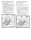
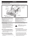
CHECKLIST
Before you operate your snow thrower, please review
the following checklist to help ensure that you will
obtain the best performance from your snow thrower.
• Makesureallassemblyinstructionshavebeen
completed with all bolts and nuts properly tightened.
• Makesurethecorrectdrivebeltwasinstalled.
• Makesurethedrivebeltandaugerbeltarerouted
properly around pulleys and inside all belt keepers.
• Checkdischargechuteforproperrotation.
• Checkoperationoftiltcontrolforupperchute.
• Verifythatthelifthandlewilllockintoandrelease
from the raised transport position. (Refer to the
ServiceandAdjustmentssection.)
• Checkskidshoeadjustment.(RefertotheService
and Adjustments section.)
The following additional items are available from
Sears to help enhance the performance of your snow
thrower. See Accessories and Attachments on page 2.
• Tirechainswhichcanbeinstalledtoimprovetraction.
• Rearwheelweightswhichcanbeinstalledinaddition
totherearweighttraytoimprovetraction.
• Driftcutterbarswhichcanbeinstalledtohelpsliceoff
the edges of tall drifts.
• SnowCabwhichcanbeinstalledtohelpprotect
against wind and blowing snow.
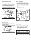
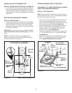
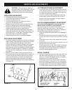
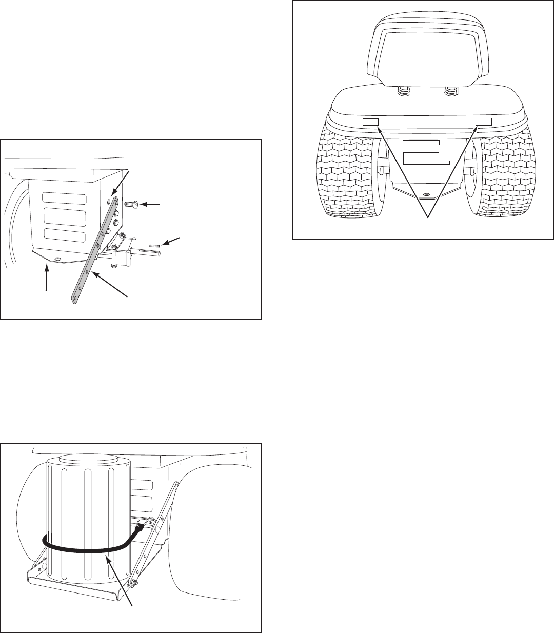
REAR REFLECTORS (QQ)
ATTACH REFLECTORS TO REAR FENDER
STEP 65: (SEE FIGURE 63)
• Ifyourtractorisnotequippedwithrearreectors,
assemblethesuppliedrearreectors(QQ)totherear
fender.Placethereectorsasclosetothebottomof
the fender and as far apart as the shape of the fender
will allow.
FIGURE 63
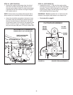
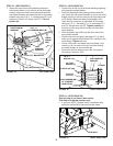
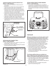
ATTACHING KEG TO WEIGHT TRAY
STEP 64: (SEE FIGURE 62)
• Place theplastic keg onthe weighttray andll with
approximately 75 lbs. of dry sand.
• Securethekegwiththerubbertarpstrap(FF)hooked
into the holes in the cross brace.
FIGURE 62
TARP STRAP (FF)
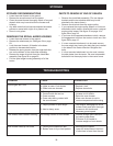
FIGURE 61
3/8" x 1" SLOTTED
TRUSS HEAD BOLT (J)
SQUARE KEY
SIDE BRACE
HOLE WITH HEX
BOLT REMOVED
TRACTOR
HITCH
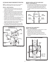
ALTERNATE INSTRUCTIONS FOR WEIGHT TRAY
STEP 63: (SEE FIGURE 61)
• Blockuptherearofthetractortoallowremovalof
rear wheels.
• Removetherearwheelsfromtheaxle,retainingthe
square key and all other parts for reassembly.
• Removethehexboltfromthetopholeinthesideof
the tractor frame. If no bolt is present and the hole is
unthreaded, screw a 3/8" x 3/4" self threading bolt (H)
into and out of the hole to create threads.
• Assemblethenotchedendofeachsidebracetothe
top hole in the each side of the tractor frame, using a
3/8-16 x 1" slotted truss head bolt (J) for each brace.
• Assembletheweighttraytothesidebracesas
instructed in step 60 or 62 on pages 24 and 25.
• Reassemblethewheelsontotheaxle,makingsureto
reassemble the square keys and all other parts which
wereremoved.