


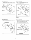
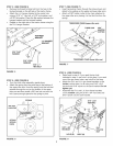
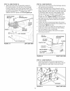

STEP5: (SEE FIGURE 5)
• Remove the thread forming bolt from the hole in the
footrest bracket on the left side of the tractor frame.
• Attach the L.H. hanger bracket to the empty hole
using a 5/16" x 1" hex bolt, a 5/16" lock washer, and
a 5/16" fiat washer. Place the fiat washer between the
hanger bracket and the footrest bracket.
• Repeat on the right side of the tractor frame using the
the R.H. hanger bracket.
,.:5-:... J L.H. HANGER
' BRACKET
5/16" FLAT
WASHER
5/16" LOCK
WASHER
5/16" x 1"
HEX BOLT
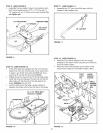
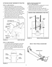
STEP 7 (SEE FIGURE 7)
* insert tensioning chains through the holes shown and
attach to the springs on the upper and lower idler arms.
* Attach a 3/32" hairpin cotter to the chain attached to
the upper idler arm, placing it in the third link from the
spring.
TENSIONING CHAIN (upper idler arm)
THIRD LINK 3/32"
HAIRPIN
TENSIONING CHAIN (lower idler arm)
FIGURE 7
FIGURE 5
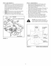
STEP 6:
e
e
(SEE FIGURE 6)
Turn the clutch idler assembly upside down.
Attach the spring from the parts bag to the bottom of
the upper idler arm. Hook the spring onto the bolt that
extends through the nut on the bottom of the upper
idler arm and then install a 3/8" hex lock nut onto the
bolt. Leave enough space for the spring to pivot.
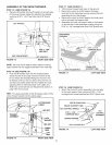
STEP 8: (SEE FIGURE 8)
• Refer back to step 4. if you used the top hole
indicated in step 4, use hole A in this step. if you used
one of the two lower holes, use hole B in this step.
Attach the R.H. and L.H. rear frame brackets on the
inside to either hole A or B using one 5/16" x 3/4"
hex bolt and 5/16" nylock nut for each bracket. Do not
tighten yet.
• Assemble the R.H. and L.H. front frame brackets
on the outside using two 5/16" x 3/4" hex bolts and
5/16" nylock nuts for each bracket.
3/8" HEX
LOCK NUT
SPRING
©
ATTACH
SPRING
HERE
FIGURE 6
5/16" x 3/4"
HEX BOLT
5/16" x 3/4"
HEX BOLT
HOLE (B) HOLE (A)
FIGURE 8
5/16"
NYLOCK
NUT