


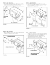
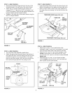
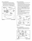
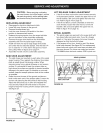

STEP19: (SEEFIGURE19)
• Attachthechutecrankrodassemblybracketsto
theplasticbracketontheleftsideofthedischarge
housing.Alignthechutecrankbracketbeneaththe
rodsupportbracketandassemblebothtotheplastic
bracketusingtwo5/16"x 1"carriagebolts,5/16"
washersand5/16"Nylocknuts.Donottightenyet.
CHUTE CRANK 5/16" x 1"
BRACKET _ CARRIAGE BOLT
\\\\\\
CHUTE
CRANK
ROD
SPIRAL
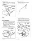
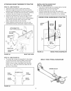
STEP 20: (SEE FIGURE 20)
Coat the top of the ring around the discharge opening
with general purpose grease.
Place the discharge chute (facing forward) onto the
ring. Place the anti-rotation bracket on top of the chute
flange, aligning it with the holes on the right hand side
of the flange. Attach the three chute keepers (right
side up as shown) to the bottom of the flange using
six 1/4" x 1" hex bolts, 1/4" flat washers and 1/4"
flanged lock nuts. Tighten carefully so that the nuts
are snug but do not dig into the plastic chute keepers.
* Place the plastic cap onto the short end of the anti-
rotation bracket.
* Position the crank rod spiral (see figure 19) so that it
does not rub against the bottoms of the notches in the
chute flange. Tighten the nuts.
* Check if the crank rod rotates the chute freely. If not,
loosen by 1/4 turn each of the six hex bolts holding
the chute keepers to the chute flange.
o Secure the control cables to the crank rod support
tube using a nylon tie.
FIGURE 19 LEFT SiDE ViEW
FIGURE 20 RIGHT SiDE ViEW
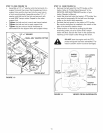
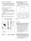
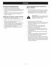
STEP 21: (SEE FIGURE 21)
If the snow thrower will not lower approximately 1"
below grade after it is attached to the tractor, remove
the stop bolts from each side of the snow thrower
frame.
13
FIGURE 21
STOP BOLT
RIGHT SiDE ViEW